
Optimizing vision correction procedures

a wavefront sensor and optical imaging technology, applied in the field of optical imaging guided vision correction procedures, can solve the problems of missing information vital to the practitioner for optimizing the optical outcome, and achieve the effect of reducing noise and improving the measurement of aberration of the ey

Inactive Publication Date: 2012-01-24
CLARITY MEDICAL SYST
View PDF14 Cites 67 Cited by
  • Summary
  • Abstract
  • Description
  • Claims
  • Application Information

AI Technical Summary

Benefits of technology

Enables real-time optimization of vision correction procedures by highlighting key aberrations, improving measurement accuracy, and reducing the need for follow-up corrections, thereby enhancing the precision and efficiency of refractive surgeries.

Problems solved by technology

Although wavefront sensors have been used to measure the refractive errors and higher order aberrations of the eye before, during, and after the dynamic vision correction process, these devices generally only produce a static snapshot display of the wavefront map of the measurement, thereby potentially missing information vital to the practitioner for optimization of the optical outcome.

Method used


Image

  • Optimizing vision correction procedures
  • Optimizing vision correction procedures
  • Optimizing vision correction procedures

Examples


Embodiment Construction

[0035]Reference will now be made in detail to various embodiments of the invention. Examples of these embodiments are illustrated in the accompanying drawings. While the invention will be described in conjunction with these embodiments, it will be understood that it is not intended to limit the invention to any embodiment. On the contrary, it is intended to cover alternatives, modifications, and equivalents as may be included within the spirit and scope of the invention as defined by the appended claims. In the following description, numerous specific details are set forth in order to provide a thorough understanding of the various embodiments. However, various embodiments may be practiced without some or all of these specific details. In other instances, well known process operations have not been described in detail in order not to unnecessarily obscure the present invention. Further, each appearance of the phrase an “example embodiment” at various places in the specification does...


PUM


Abstract

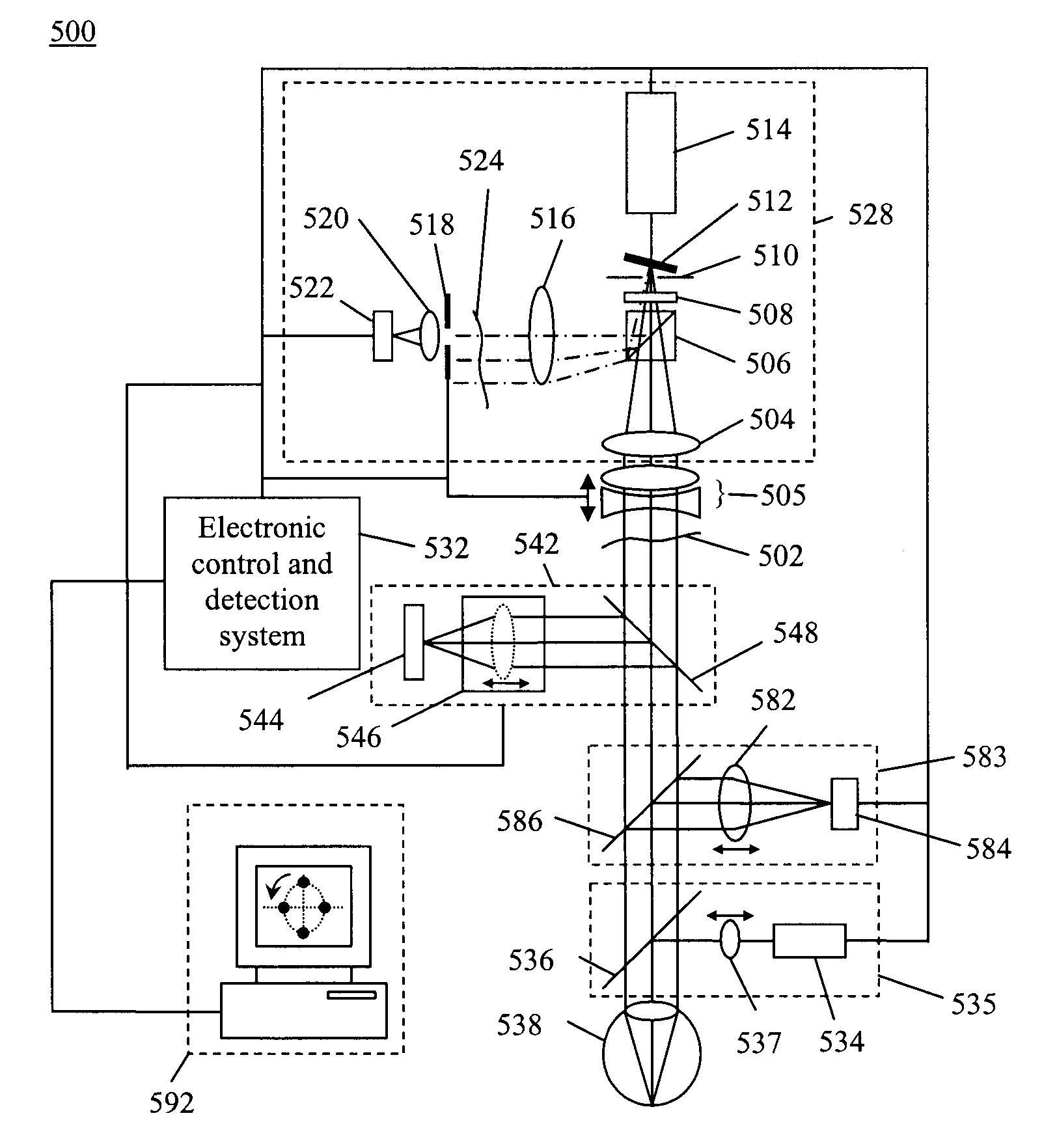
Example embodiments include a dynamic wavefront sensor, a controllable wavefront offsetting element and a controller that controls the controllable wavefront offsetting element to offset selected non-plane wave aberration components in order to allow remaining non-plane wave aberration components to be more efficiently detected and measured.

Description

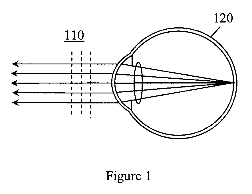
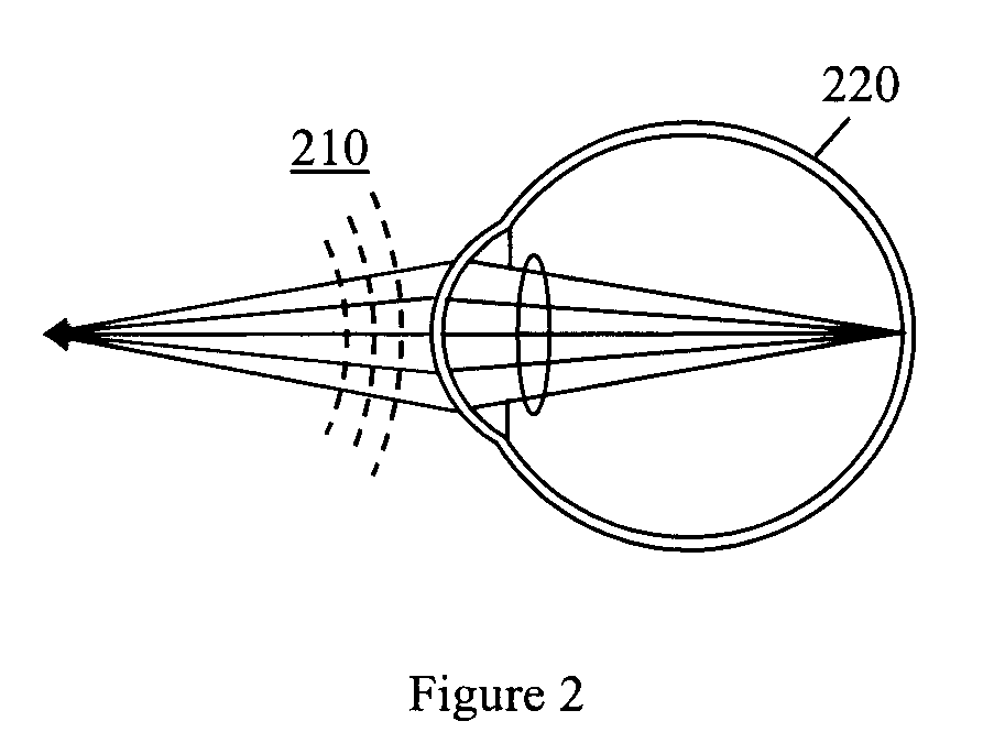
RELATED APPLICATIONS[0001]This application is a continuation of application Ser. No. 11 / 761,890 entitled Adaptive Sequential Wavefront Sensor, filed Jun. 12, 2007 now U.S. Pat. No. 7,815,310, issued Oct. 19, 2010 which is a continuation of application Ser. No. 11 / 335,980 entitled Sequential Wavefront Sensor, filed Jan. 20, 2006 now U.S. Pat. No. 7,445,335, issued Nov. 4, 2008, all of which are incorporated by reference for all purposes.TECHNICAL FIELD[0002]One or more embodiments of the present invention relate generally to ophthalmic wavefront sensors and adaptive optics systems. In particular, the invention is related to wavefront guided vision correction procedures.BACKGROUND OF THE INVENTION[0003]A wavefront sensor is a device for measuring the aberrations of an optical wavefront. Wavefront sensors have been used for eye aberration measurement by directing a narrow beam of light to the retina of an eye and sensing the optical wavefront coming out from the eye. For a relaxed emme...

Claims


Application Information

Patent Timeline
Patent Type & Authority Patents(United States)
IPC IPC(8): A61B3/10
CPCG01J9/00A61B3/14A61B3/10A61B3/1035A61B3/1015A61B3/103A61B3/0025A61B3/0091A61B3/036G01J2003/064A61B90/20A61B3/0041A61B3/13A61B5/7415
Inventor ZHOU, YANSHEA, WILLIAMLINDER, BARRYBAKER, PHILLIP
Owner CLARITY MEDICAL SYST
Learn More