
Frame structure and image forming apparatus

a frame structure and image forming technology, applied in the direction of electrographic process apparatus, instruments, optics, etc., can solve the problems of faulty scanning, affecting the accuracy of image forming,

Active Publication Date: 2012-01-17
RICOH KK
View PDF19 Cites 4 Cited by
  • Summary
  • Abstract
  • Description
  • Claims
  • Application Information

AI Technical Summary

Benefits of technology

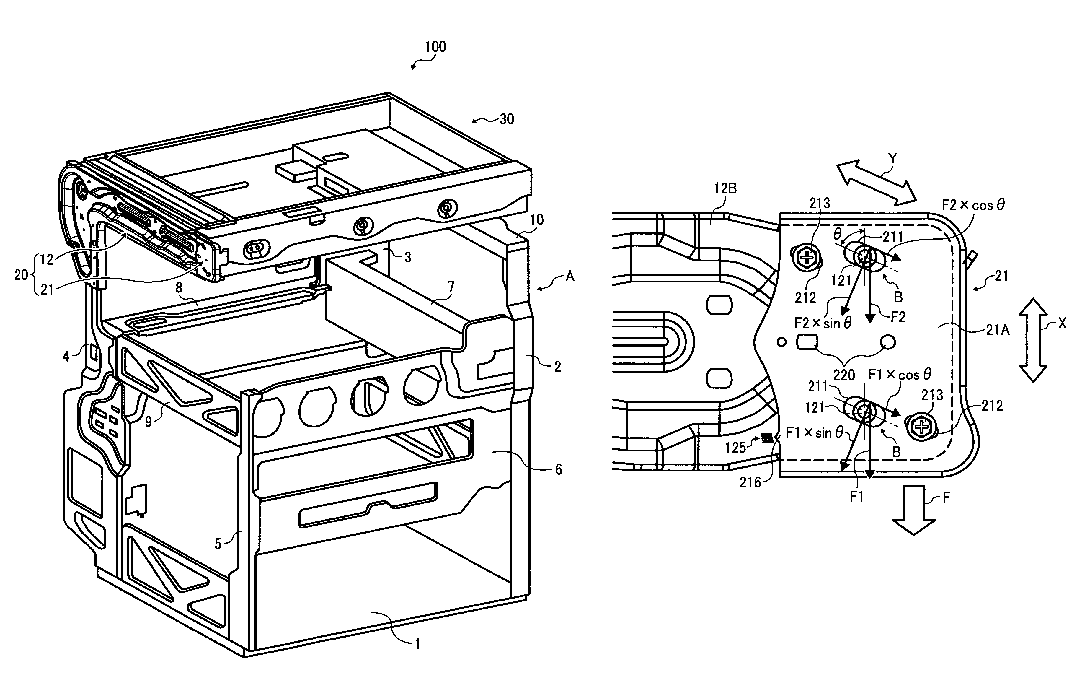
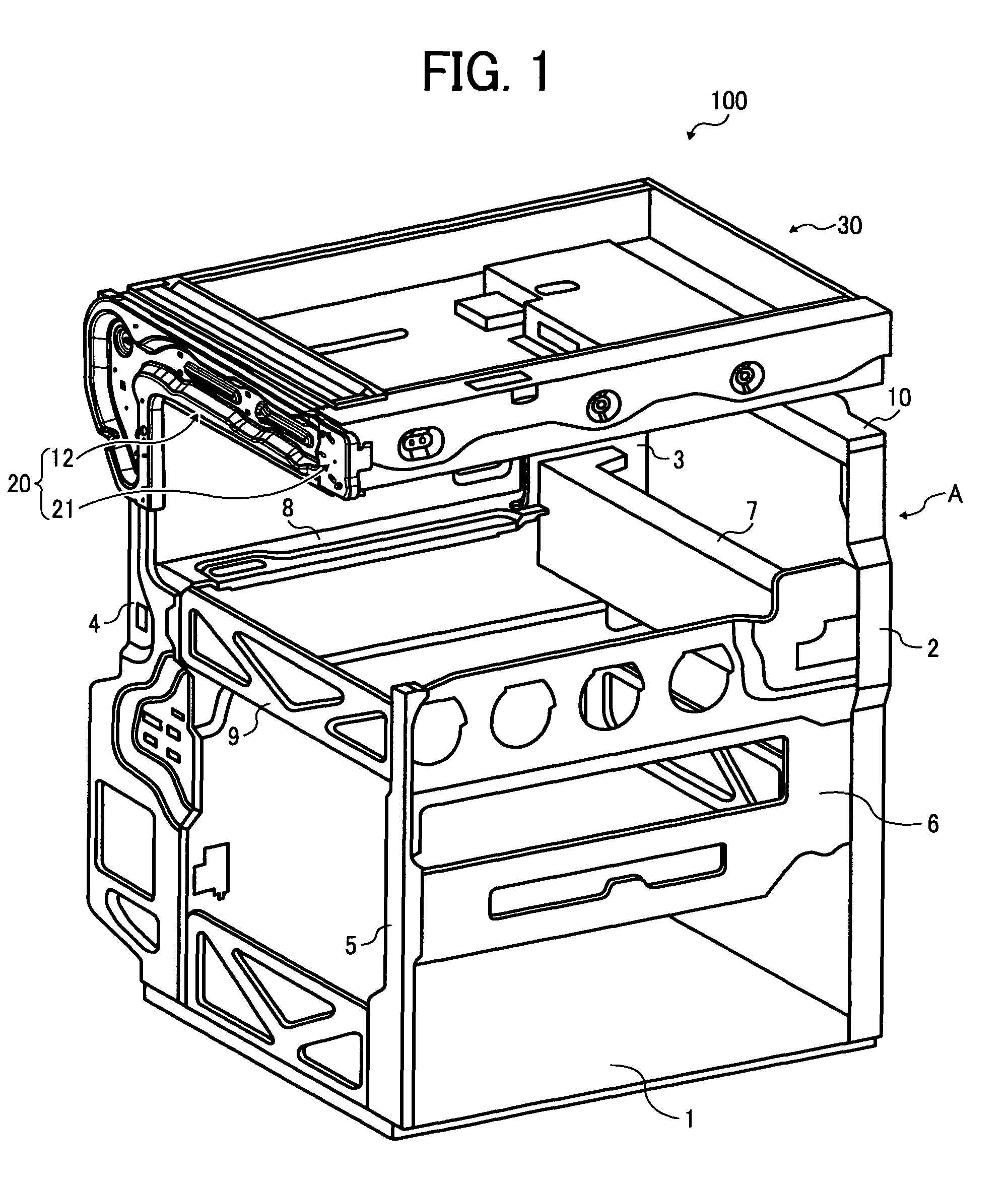
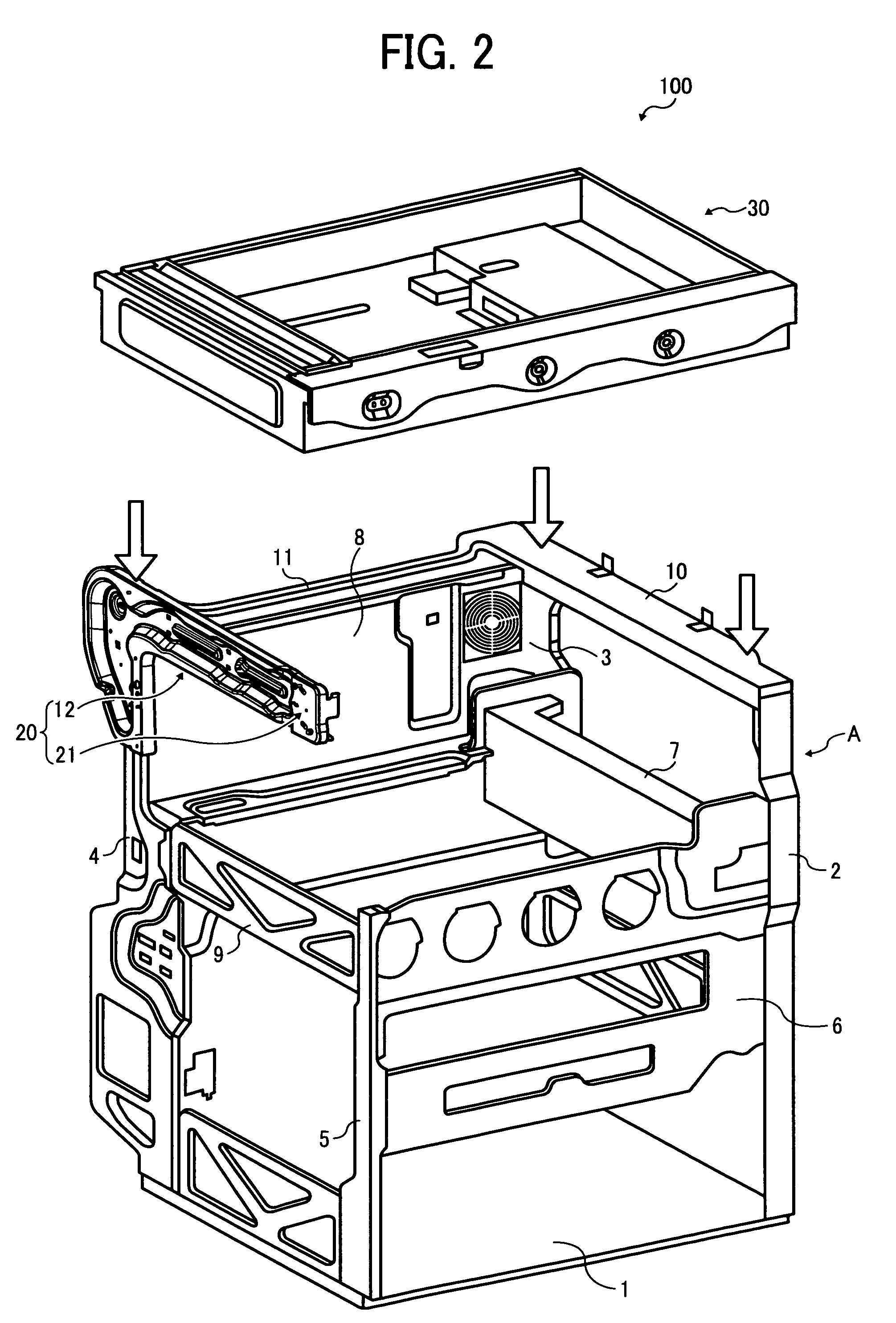
The patent text describes a frame structure for an image forming apparatus that includes three or more supporting members, a scanner support, a scanner cantilever support, and an adjuster. The scanner cantilever support extends horizontally from the upper portion of one of the supporting members and includes an inclined slot. The adjuster is attached to a free end of the cantilever support and includes a protrusion engageable with the slot of the cantilever support to obliquely raise and lower the adjuster. The technical effects of this frame structure include improved stability and reduced vibration during operation, as well as improved adjustability and flexibility for the scanner support.

Problems solved by technology

Thus, for example, when a user accidentally puts their weight on the scanner or otherwise imposes an excessive downward load on the scanner, an adjuster that is typically provided for adjusting a horizontal position of the scanner is displaced from an original position or damaged.
As a result, the scanner fails to maintain a horizontal position, resulting in faulty scanning.
In addition, when the adjuster is damaged, the adjuster needs to be adjusted or replaced by a new one, which increases cost and down time.
Therefore, the rate of utilization of the image forming apparatus decreases, while its running cost and maintenance cost increase.

Method used


Image

  • Frame structure and image forming apparatus
  • Frame structure and image forming apparatus
  • Frame structure and image forming apparatus

Examples


Embodiment Construction

[0025]It will be understood that if an element or layer is referred to as being “on”, “against”, “connected to”, or “coupled to” another element or layer, then it can be directly on, against, connected or coupled to the other element or layer, or intervening elements or layers may be present. In contrast, if an element is referred to as being “directly on”, “directly connected to”, or “directly coupled to” another element or layer, then there are no intervening elements or layers present. Like numbers refer to like elements throughout. As used herein, the term “and / or” includes any and all combinations of one or more of the associated listed items.

[0026]Spatially relative terms, such as “beneath”, “below”, “lower”, “above”, “upper”, and the like, may be used herein for ease of description to describe one element or feature's relationship to another element(s) or feature(s) as illustrated in the figures. It will be understood that the spatially relative terms are intended to encompas...


PUM


Abstract

A frame structure includes three or more supporting members, a scanner support, a scanner cantilever support, and an adjuster. Three or more supporting members are provided vertically from a base portion. The scanner support is provided horizontally between upper portions of the supporting members. The scanner cantilever support extends horizontally from the upper portion of one of the supporting members. The adjuster is attached to a free end of the cantilever support, and includes an inclined slot. The cantilever support includes a protrusion provided in the free end of the scanner cantilever support. The protrusion is engageable with the slot of the adjuster to obliquely raise and lower the adjuster.

Description

PRIORITY STATEMENT[0001]The present patent application claims priority from Japanese Patent Application No. 2008-048353, filed on Feb. 28, 2008 in the Japan Patent Office, the entire contents of which are hereby incorporated herein by reference.BACKGROUND OF THE INVENTION[0002]1. Field of the Invention[0003]Example embodiments generally relate to a frame structure and an image forming apparatus including the frame structure, for example, in which the frame structure has a compact structure that efficiently supports a scanner.[0004]2. Description of the Related Art[0005]Image forming apparatuses, such as copiers, facsimile machines, printers, and multifunction devices having at least one of copying, printing, scanning, and facsimile functions, typically form a toner image on a recording medium (e.g., a sheet) based on image data using electrophotography.[0006]When an image forming device forms a toner image on a sheet conveyed from a feeding device, the sheet bearing the toner image ...

Claims


Application Information

Patent Timeline
Patent Type & Authority Patents(United States)
IPC IPC(8): G03G15/00
CPCG03G15/60G03G21/1619G03G2221/1654G03G2221/1678
Inventor TAKEMOTO, HIDEYUKI
Owner RICOH KK
Learn More