
Downhole combustion unit and process for TECF injection into carbonaceous permeable zones

a combustion unit and carbonaceous permeable technology, applied in the direction of fluid removal, borehole/well accessories, insulation, etc., can solve the problems of no prior art patented method and system using compressed air and gas technology, no prior art patented method and system, and laborious combustion furnaces. , to achieve the effect of low cost, easy conversion, and little research and development tim

Inactive Publication Date: 2012-01-10
HILL GILMAN A +1
View PDF7 Cites 2 Cited by
  • Summary
  • Abstract
  • Description
  • Claims
  • Application Information

AI Technical Summary

Benefits of technology

"The patent describes a new combustion unit for use in in-situ retorting of carbonaceous deposits in underground deposits. The unit creates a high-temperature, high-pressure gas called TECF, which is injected into the formation to remove the deposits. The unit is simple and low-cost, and can use unburned gases and water produced from the formation. The unit can be easily converted between an injection well and a production well. The combustion unit includes an outer well-bore casing and an inner well-bore casing with injection holes for receiving fuel, water, compressed air, and steam, which mix in the combustion chamber and create the high-temperature, high-pressure gas. The gas is then discharged out the bottom of the unit and into the formation. The technical effects of this invention include improved efficiency and control in the in-situ retorting process and reduced costs for well construction and operation."

Problems solved by technology

Consequently, the elaborate, pollutant-free combustion furnaces, with catalytic converters have no advantage, but many detriments for in-situ retorting applications.
None of the prior art patented methods and systems using compressed air and gas technology with boreholes have used a combustion unit as described herein for creating one or more large, thermal-energy heating elements in a permeable hydrocarbon zone.

Method used


Image

  • Downhole combustion unit and process for TECF injection into carbonaceous permeable zones
  • Downhole combustion unit and process for TECF injection into carbonaceous permeable zones
  • Downhole combustion unit and process for TECF injection into carbonaceous permeable zones

Examples


Embodiment Construction

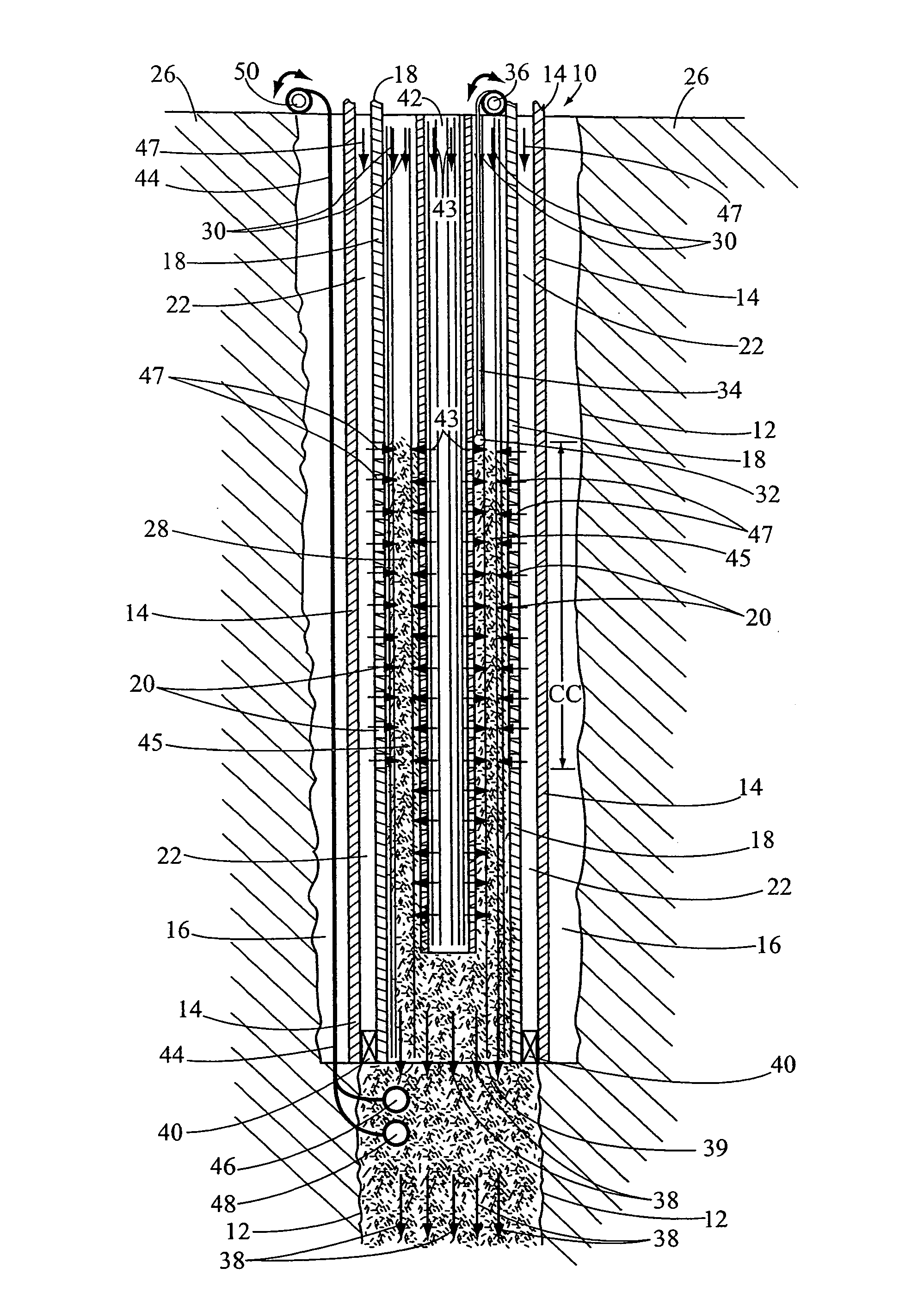
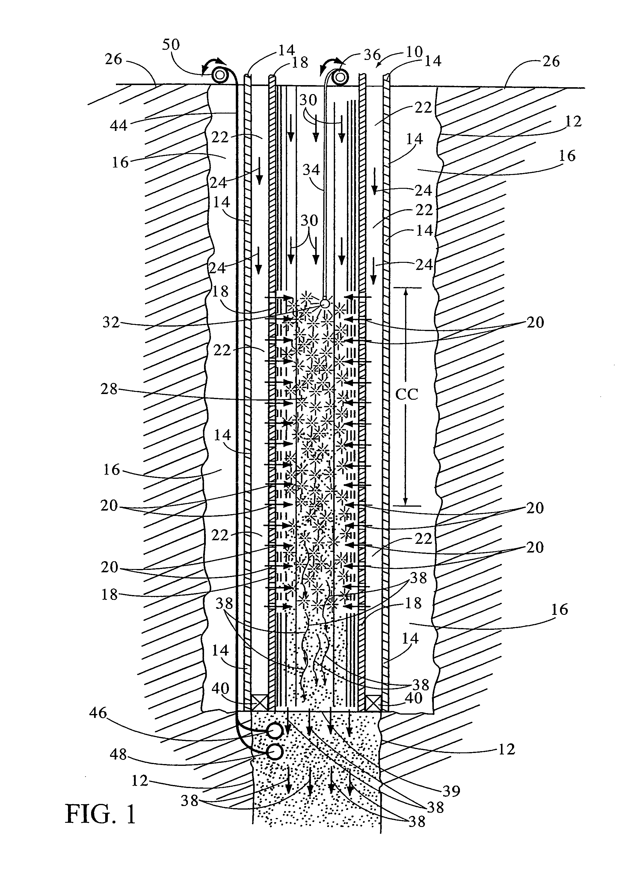
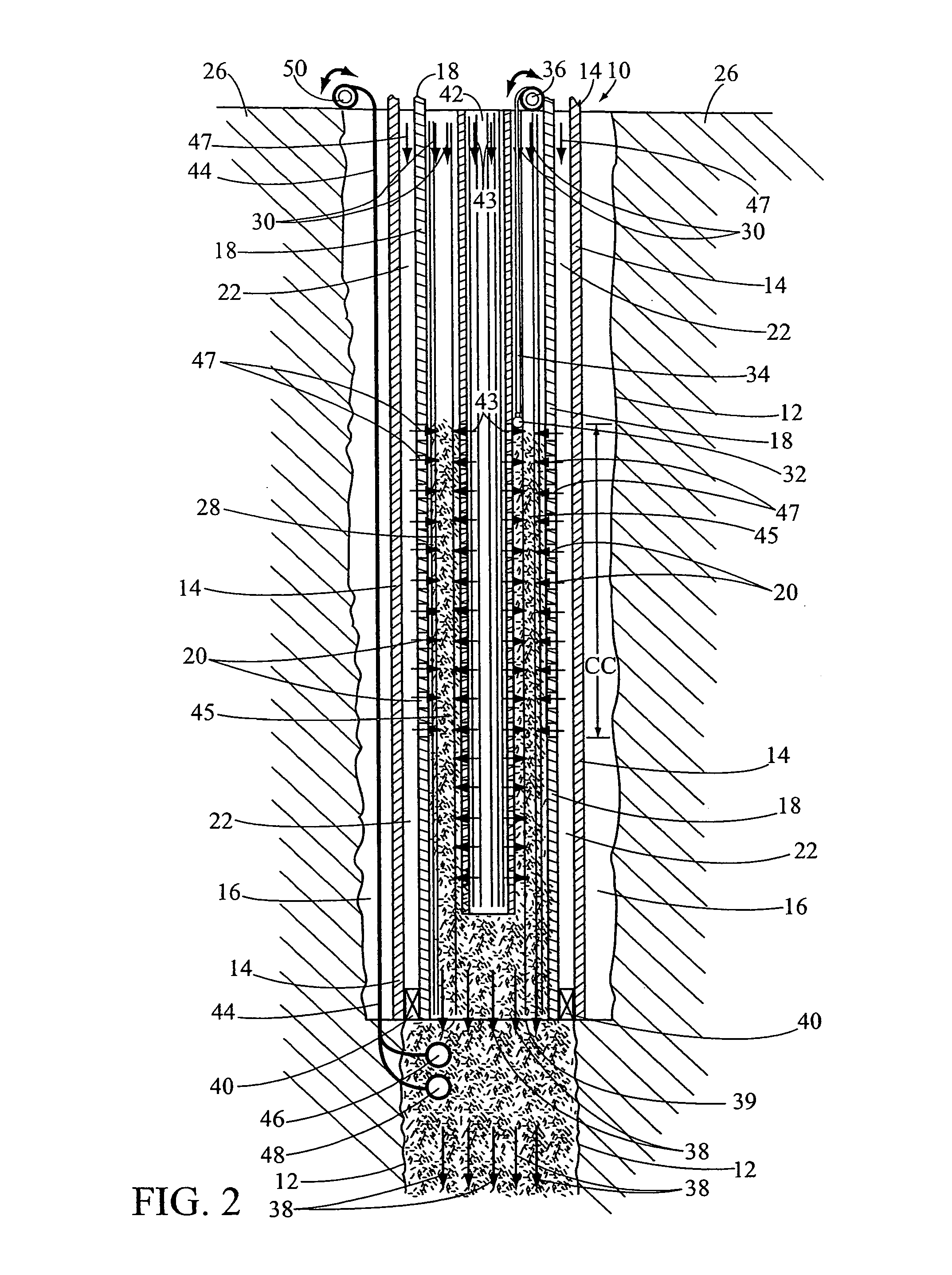
[0015]In FIG. 1, a cross-sectional view of the subject downhole-combustion unit, having general reference numeral 10, is shown installed in a drill hole 12. A well-bore outer casing 14 is held in place next to the drill hole 12 using cement 16. A well-bore inner casing 18, with injection holes 20 in a lower portion thereof, is suspended inside the outer casing 14. The configuration of the concentric casing 14 and 18 provide an outer annulus 22 for receiving a natural gas fuel and water mixture, indicated by arrows 24, therebetween from a ground surface 26 and circulated downwardly under pressure.

[0016]The outer casing 14 typically has, but not limited to, a 13⅜ inch OD and 12.347 inch ID, 72 lb / ft casing, such as N-80 or C-75 grade, standard, oil field steel casing. Also, the suspended inner casing 18 typically has, but not limited to, a 9⅝ inch OD and 8.835 inch ID, 40 lb / ft casing, such as N-80, C-75, or J-55 grade, standard, oil field steel casing. Using this size of oil field ca...


PUM


Abstract

A downhole combustion unit for creating a high temperature, high pressure, thermal energy carrier fluid (TECF) inside a drill hole, which can be injected into a hydrocarbon, permeable zone for mining and producing hydrocarbons therefrom. The combustion unit includes an outer well-bore casing cemented in place in the drill hole. An inner well-bore casing, with injection holes in a lower portion thereof is used as a combustion chamber. The inner casing is suspended inside the outer casing. The configuration of the concentric outer and inner casings provide an outer annulus therebetween for receiving water from a ground surface and circulated downwardly under pressure. Compressed air and steam are circulated down the inside of the inner casing. A gas fuel tubing is disposed inside the inner casing for discharging the fuel into the combustion chamber. A glow plug may be attached to a lower end of an electric power cable and suspended inside the combustion chamber for better control in igniting the fuel and water mixture in the compressed air and steam mixture creating the TECF. The TECF is discharged out the bottom of the combustion unit into a permeable, hydrocarbon zone.

Description

[0001]This patent application is a Divisional patent application of an application titled “Downhole Combustion Unit and Process for TECF Injection into Carbonaceous Permeable Zones, Ser. No. 12 / 317,980, filed on Dec. 31, 2008 now U.S. Pat. No. 7,784,533. The latter application is a Continuation-In-Part patent application of a prior Utility Patent Application, titled “Integrated In-situ Retorting And Refining Of Oil Shale,” filed on Jun. 19, 2006, Ser. No. 11 / 455,438, by Gilman A. Hill and Joseph A. Affholter, and a prior Continuation patent application of the Utility Patent Application, titled “Integrated In-situ Retorting and Refining of Heavy-Oil and Tar Sand Deposits”, filed on Aug. 26, 2006, Ser. No. 11 / 510,751, by Gilman A. Hill and Joseph A. Affholter. Also, the applicant / inventor claims the benefit of a Provisional Patent Application, titled “Downhole-Combustion Unit for TECF Injection”, as filed on Jan. 2, 2008, Ser. No. 61 / 009,895, by Gilman A. Hill.BACKGROUND OF THE INVENT...

Claims


Application Information

Patent Timeline
Patent Type & Authority Patents(United States)
IPC IPC(8): E21B36/02
CPCE21B43/243
Inventor HILL, GILMAN A.AFFHOLTER, JOSEPH A.
Owner HILL GILMAN A
Learn More