
Automated wing painting system

a technology of automatic wing painting and wing surface, which is applied in the direction of superimposed coating process, liquid/solution decomposition chemical coating, manufacturing tools, etc., can solve the problems of time, space, labor, and materials, and the time needed to schedule a crane for a move and have the crane arrive may take a number of hours

Active Publication Date: 2012-01-03
THE BOEING CO
View PDF11 Cites 12 Cited by
  • Summary
  • Abstract
  • Description
  • Claims
  • Application Information

AI Technical Summary

Benefits of technology

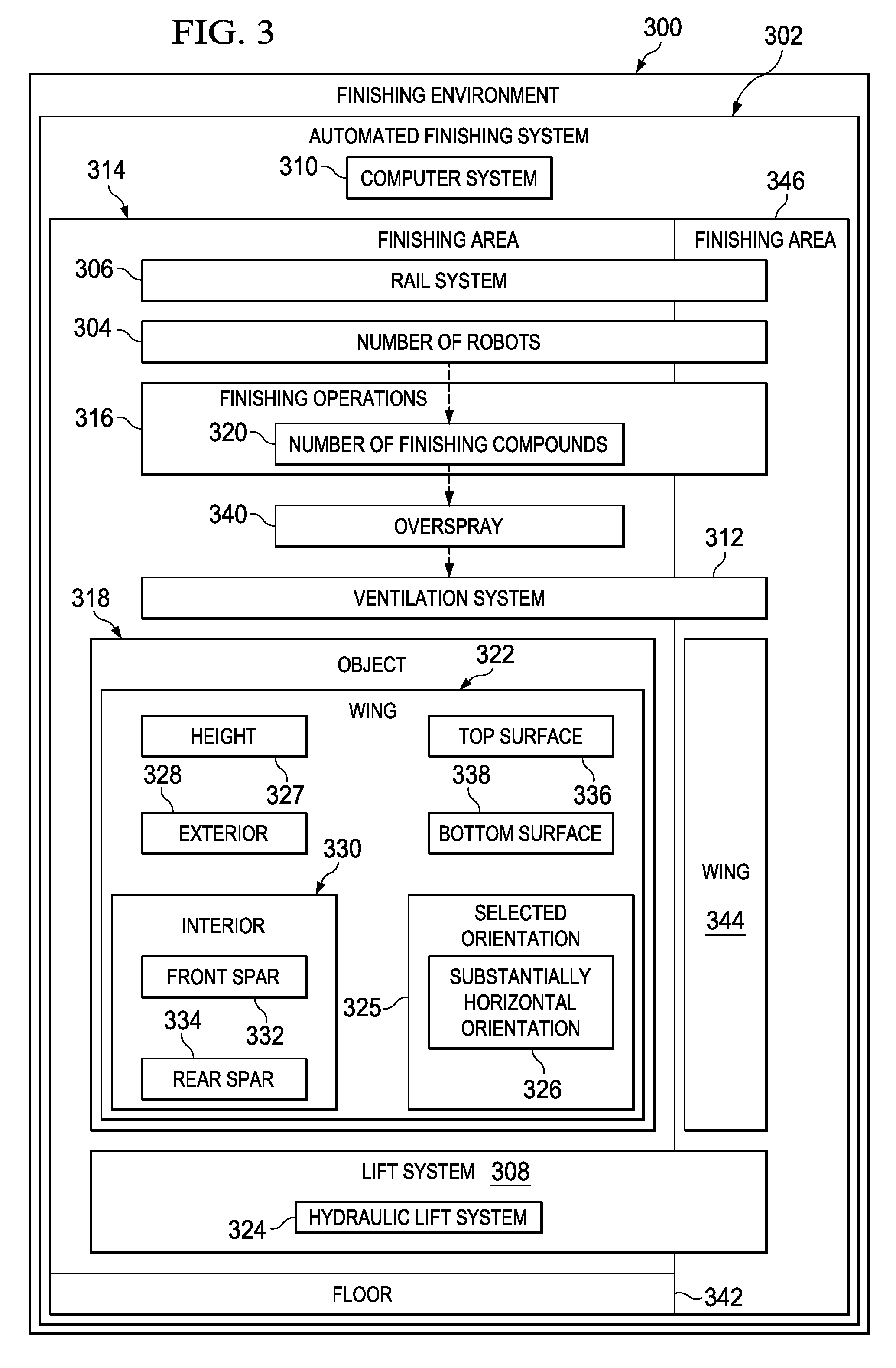
The patent describes an automated finishing system that uses a lift system and robots to apply finishing compounds to an object in a horizontal position. The system can position the object in a selected orientation and apply finishing compounds to both the interior and exterior of the object. The technical effects of this system include improved efficiency, accuracy, and consistency in finishing, as well as reduced labor costs and improved safety.

Problems solved by technology

This type of process requires labor, time, space, and materials.
For example, moving the wing from a horizontal orientation to a vertical orientation takes a number of hours.
Further, the time needed to schedule a crane for a move and have the crane arrive also may take a number of hours.
As a result, the process of scheduling a crane, having the crane and crane crew arrive, and moving the wing may take around eight hours.

Method used


Image

  • Automated wing painting system
  • Automated wing painting system
  • Automated wing painting system

Examples


Embodiment Construction

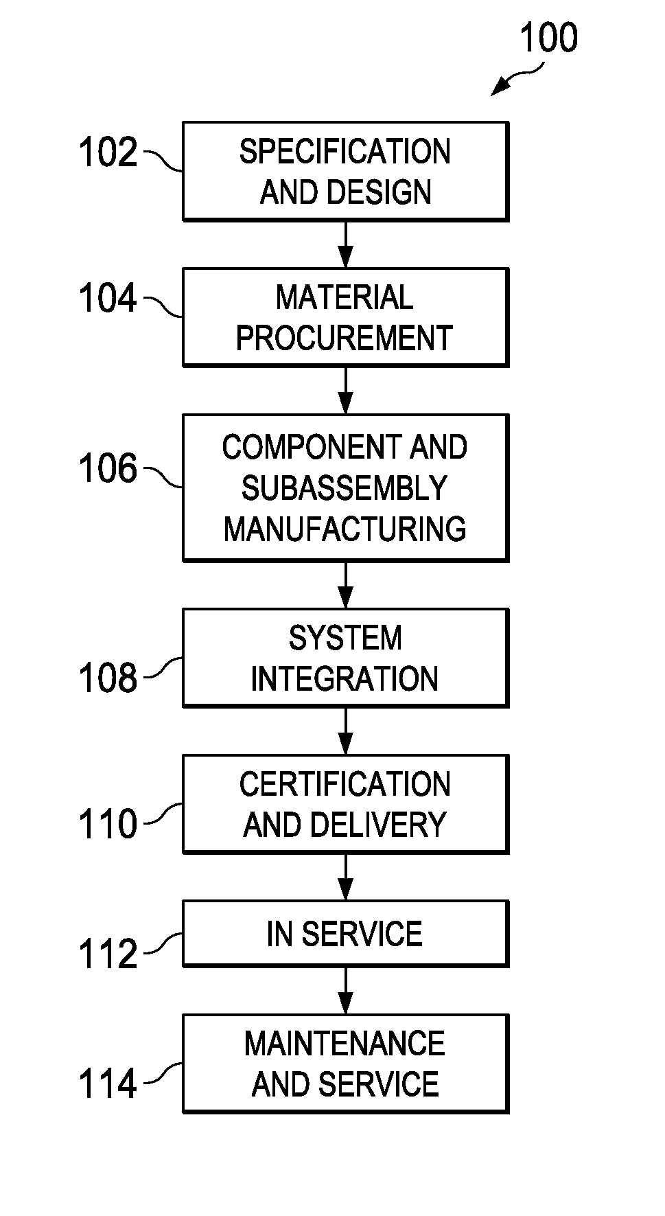
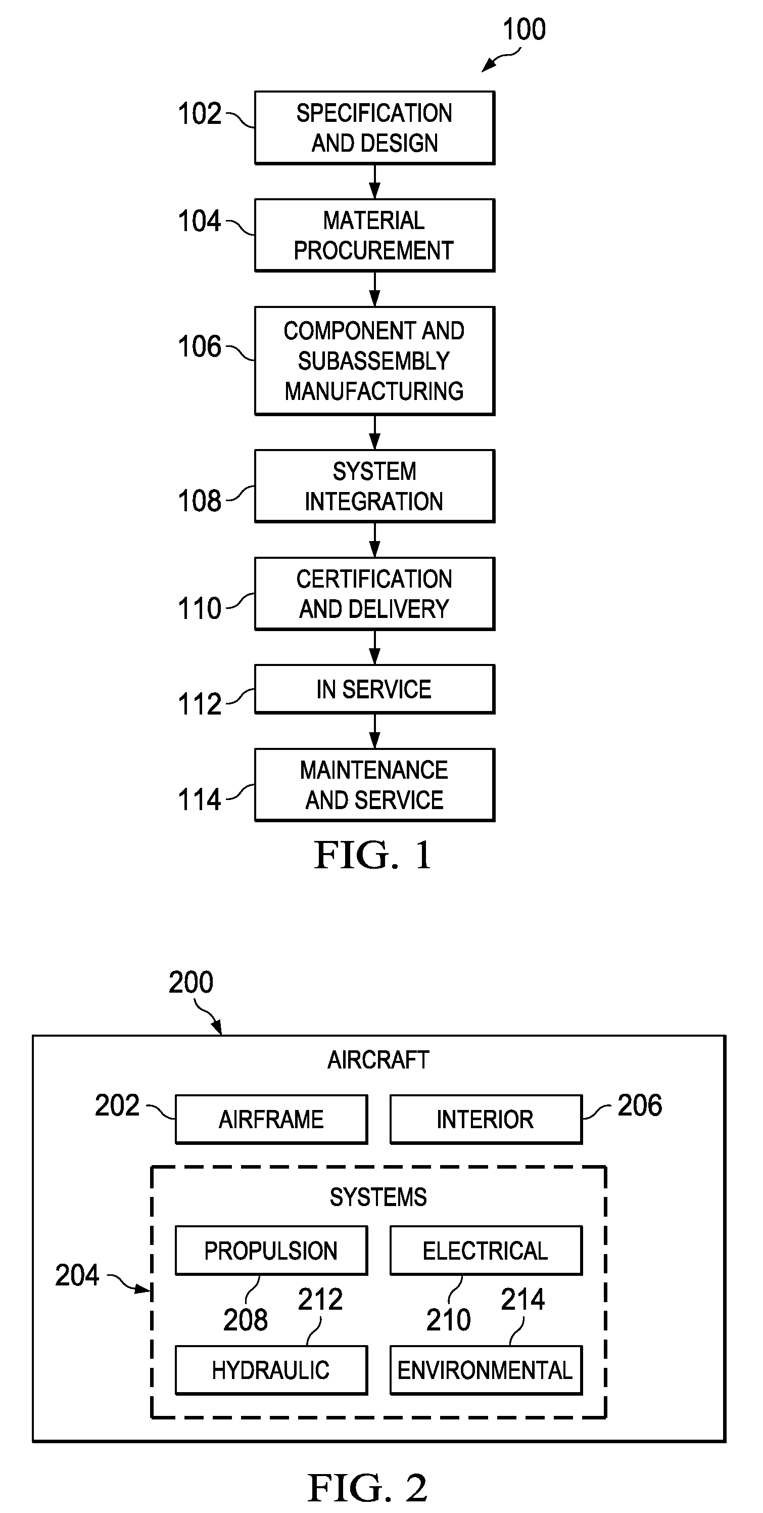
[0029]Referring more particularly to the drawings, embodiments of the disclosure may be described in the context of aircraft manufacturing and service method 100 as shown in FIG. 1 and aircraft 200 as shown in FIG. 2. Turning first to FIG. 1, a diagram illustrating an aircraft manufacturing and service method is depicted in accordance with an advantageous embodiment. During pre-production, exemplary aircraft manufacturing and service method 100 may include specification and design 102 of aircraft 200 in FIG. 2 and material procurement 104.

[0030]During production, component and subassembly manufacturing 106 and system integration 108 of aircraft 200 in FIG. 2 takes place. Thereafter, aircraft 200 in FIG. 2 may go through certification and delivery 110 in order to be placed in service 112. While in service by a customer, aircraft 200 in FIG. 2 is scheduled for routine maintenance and service 114, which may include modification, reconfiguration, refurbishment, and other maintenance or ...


PUM

PropertyMeasurementUnit
timeaaaaaaaaaa
timeaaaaaaaaaa
heightaaaaaaaaaa

Abstract

An automated finishing system comprises a lift system and a number of robots. The lift system is capable of positioning a wing in a substantially horizontal position. The number of robots is capable of applying a number of finishing compounds to at least one of an interior of the wing and an exterior of the wing, while the wing remains in the substantially horizontal position.

Description

BACKGROUND INFORMATION[0001]1. Field:[0002]The present disclosure relates generally to manufacturing structures and, in particular, to a method and apparatus for painting structures. Still more particularly, the present disclosure relates to a method and apparatus for painting a wing for an aircraft.[0003]2. Background:[0004]In manufacturing aircraft, machines, tools, human labor, materials, and / or other suitable items may be used to assemble structures. These structures may include, for example, without limitation, a wing, a fuselage, a rudder, or some other suitable structure.[0005]Part of the manufacturing process includes finishing structures prior to assembly. For example, a wing of an aircraft may be painted prior to attaching the wing to a fuselage. The painting of a wing may occur for a number of different reasons. For example, the exterior of the wing may be painted to provide better airflow, for aesthetic reasons, to prevent corrosion, and / or for other purposes. The interi...

Claims


Application Information

Patent Timeline
Patent Type & Authority Patents(United States)
IPC IPC(8): B05D7/00
CPCB05B13/005B05B13/0431B05B15/1214B25J9/0084B64F5/0009B64F5/0018B05B15/1207B25J5/02B05B13/041B05B13/06B05B15/1225B64F5/10B64F5/30B05B16/20B05B16/40B05B14/40
Inventor SWANBERG, JEFFERY P.BREWER, KENNETH R.KAKALECIK, STEVEN J.DUNHAM, CODY S.STOUFFER, ROBERT J.DEROUIN, MARTIN F.
Owner THE BOEING CO
Learn More