
Dual lever steering controls with control stops

a control stop and control lever technology, applied in the direction of non-deflectable wheel steering, mechanical equipment, transportation and packaging, etc., can solve the problems of reducing the service life of the mower, slipping of the inside wheel, and destroying the turf of the mower, so as to reduce the damage to the turf or eliminate the effect of damag

Active Publication Date: 2012-01-03
DEERE & CO
View PDF10 Cites 12 Cited by
  • Summary
  • Abstract
  • Description
  • Claims
  • Application Information

AI Technical Summary

Benefits of technology

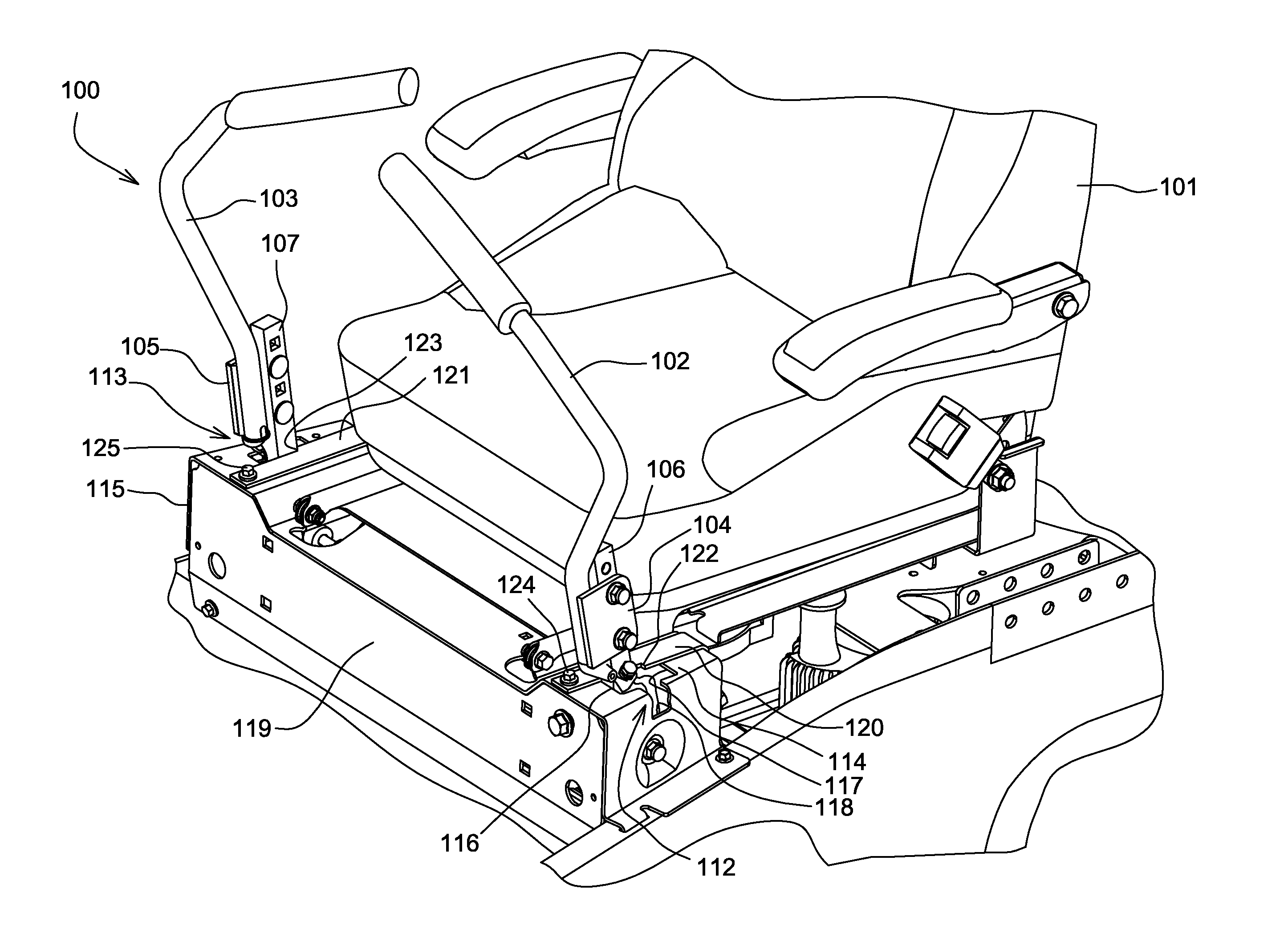
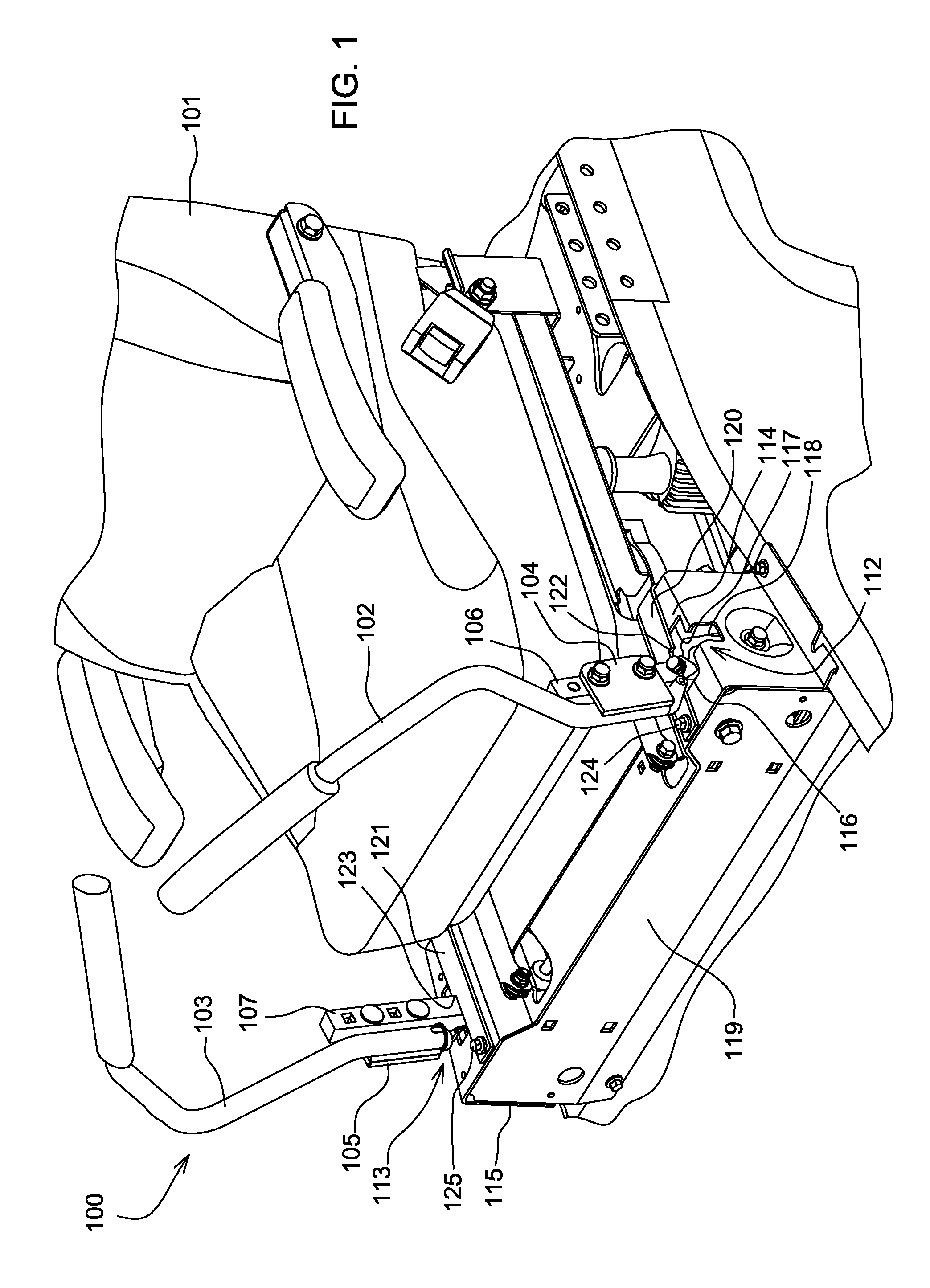
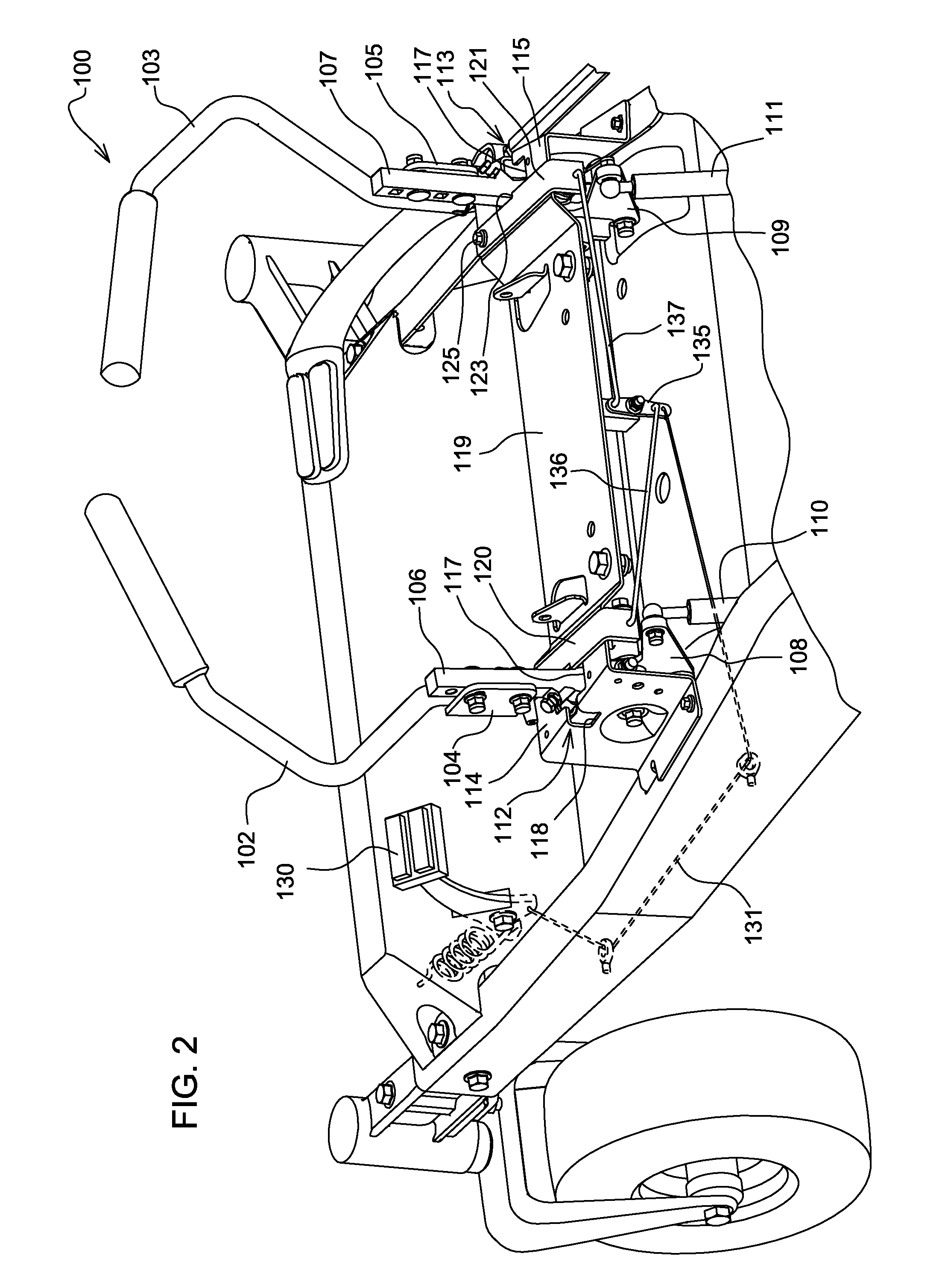
[0006]Dual lever steering controls for a zero turning radius mower include control stops that prevent the inside wheel from slowing under a minimum forward speed during a turn. Each control stop may prevent a steering control from pivoting below a minimum forward speed position. When the operator pivots the lever or stick to slow the wheel, the steering control abuts the control stop at a position that ensures the wheel continues turning forward at the minimum forward speed. As a result, turf damage is minimized or eliminated. The control stops also may allow the operator to slow the wheel under the minimum speed, stop the wheel, or turn the wheel in reverse. For example, each control stop may be biased to the minimum forward speed position, or the lever or stick may be pivoted around the control stop. Additionally, the control stops may be retracted to a non-operating position.

Problems solved by technology

However, if one lever or stick is pivoted forward and the other is at or near the neutral position, the ZTR mower's inner wheel has a tendency to damage the turf.
During very short, small radius turns, the inside wheel that stops or turns very slowly may slide and scrape the grass where the inside wheel is positioned.

Method used


Image

  • Dual lever steering controls with control stops
  • Dual lever steering controls with control stops
  • Dual lever steering controls with control stops

Examples


second embodiment

[0022]Alternatively, in a second embodiment shown in FIG. 3, solenoid 140 may be attached to platform 119, and may be wired to switch 141 and battery 142. When the switch is actuated, the solenoid may turn crank 145, pulling left and right control stop links 146, 147 laterally inwardly. Each control stop link is connected to a control stop which can pivot to a non-operating position.

third embodiment

[0023]In a third embodiment shown in FIG. 4, left control lever 102 is shown with control stop 150. Control stop 150 is mounted on plate 114 at the reverse end of the T-shaped slot. In the operating position, the control stop may provide a minimum forward speed. The control stop may be positioned to block or resist pivotal movement of neutral position lever 106 below a minimum forward speed. By locating the control stop at a minimum forward speed position, the control stop can block or stop the inside control lever or stick from pivoting to a slower speed, or into neutral or reverse, during turns. Additionally, the minimum forward speed position of the control stop may be set by adjustable cam 152. The adjustable cam may pivot to provide a camming surface that locates the control stop at the neutral position lever at the minimum forward speed position until the operator exerts a greater force on the control lever or stick to overcome the control stop.

[0024]In the embodiment of FIG. ...


PUM


Abstract

Dual lever steering controls with control stops are provided for a zero turning radius mower. Each control arm is mounted to a neutral position lever that is pivotable between a full forward drive position and a full reverse drive position. Each control stop is mounted to block the control arm and neutral position lever from pivoting to a position under a minimum forward speed. Each control stop may be biased to the minimum forward speed position, and also may be pivotable between an operating position and a non-operating position.

Description

FIELD OF THE INVENTION[0001]This invention relates to grass mowing machines, and specifically to zero turning radius (“ZTR”) mowers having independently powered left and right drive wheels controlled by a pair of control levers or sticks.BACKGROUND OF THE INVENTION[0002]Grass mowing machines known as zero turning radius (“ZTR”) mowers have at least one independently powered drive wheel on each side of a frame. One drive wheel may be operated in a forward direction while the other drive wheel may be stopped or operated in reverse. Many ZTR mowers have a twin stick control system. A pair of control levers or sticks may be provided side-by-side, with each lever or stick controlling one of the drive wheels. When both levers or sticks are advanced together forwardly out of their neutral position, both drive wheels rotate forwardly to cause the mower to move forward. A ZTR mower may be steered by advancing one lever or stick more than the other.[0003]Typically, each control lever or stick...

Claims


Application Information

Patent Timeline
Patent Type & Authority Patents(United States)
IPC IPC(8): B62D7/00
CPCA01D34/69A01D34/64Y10T74/20256A01D2034/6843
Inventor TREFZ, HARLIN J.HUTCHISON, WAYNE R.
Owner DEERE & CO
Learn More