
Advanced frequency calibration

a frequency calibration and frequency technology, applied in the direction of resistance/reactance/impedence, static indicating devices, instruments, etc., can solve the problems of inability to report a single point, lack of ability to track multiple points of contact at the same time, and the deterioration of most circuit based oscillators

Active Publication Date: 2011-12-27
APPLE INC
View PDF32 Cites 29 Cited by
  • Summary
  • Abstract
  • Description
  • Claims
  • Application Information

AI Technical Summary

Benefits of technology

The patent describes a circuit that generates a precise oscillating signal using an external reference. The circuit includes calibration logic to compare the local signal to the reference and adjust it to the desired frequency. The calibration logic can use a binary search algorithm or other methods to find the optimal frequency. The circuit can also include a voltage or current controlled oscillator and can output the oscillating signal to circuits that are sensitive to frequency. The calibration logic can continuously monitor the local signal and adjust its frequency as needed. The technical effect of this patent is to provide a reliable and efficient way to generate precise oscillating signals for various circuits.

Problems solved by technology

One limitation of many conventional touch panel technologies is that they are only capable of reporting a single point or touch event, even when multiple objects come into contact with the sensing surface.
That is, they lack the ability to track multiple points of contact at the same time.
Moreover, many touch-panel devices use oscillating signals to power and clock electronic elements.
However, most circuit based oscillators suffer from the fact that they do not provide a signal with a precise and predictable frequency.

Method used


Image

  • Advanced frequency calibration
  • Advanced frequency calibration
  • Advanced frequency calibration

Examples


Embodiment Construction

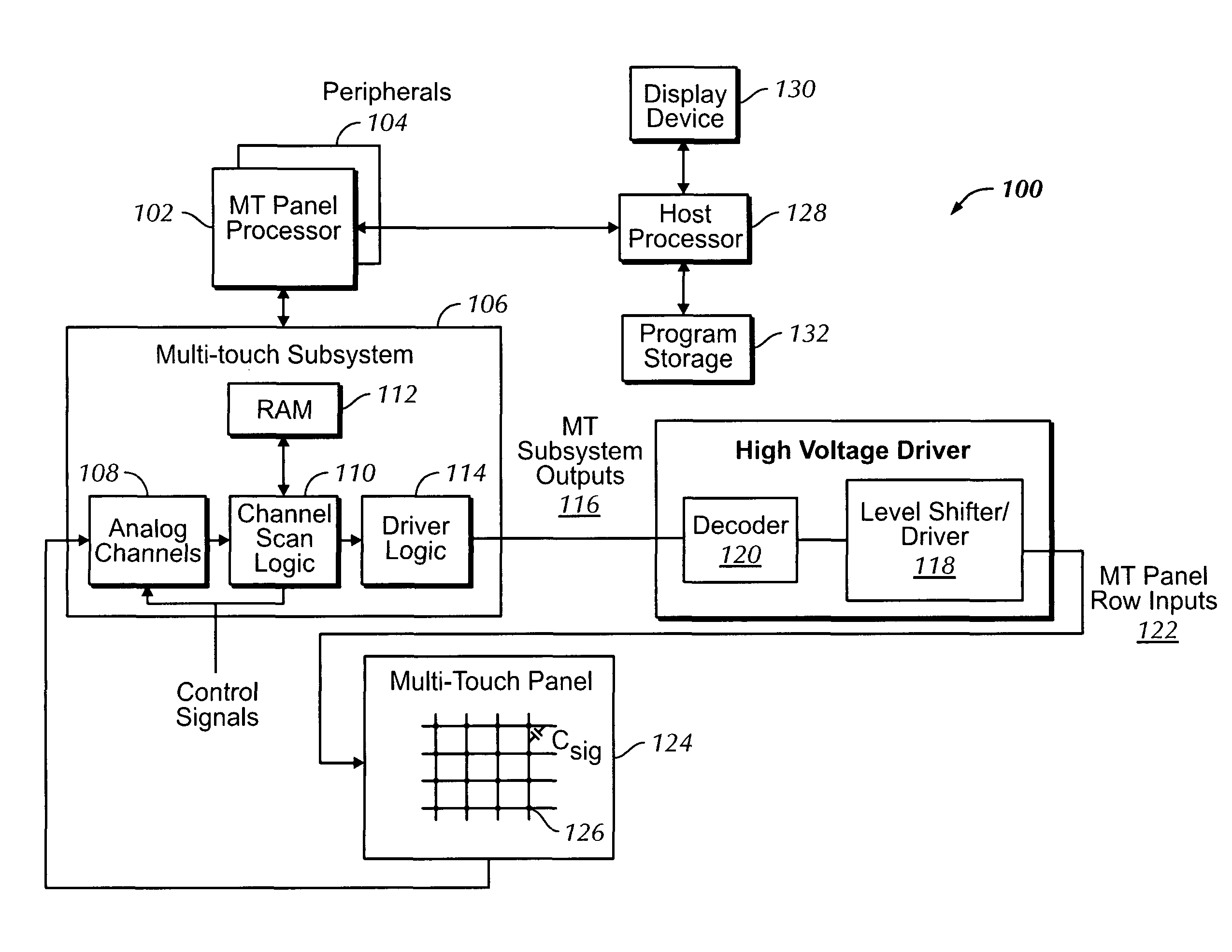
[0023]In the following description of preferred embodiments, reference is made to the accompanying drawings which form a part hereof, and in which it is shown by way of illustration specific embodiments in which the invention may be practiced. It is to be understood that other embodiments may be used and structural changes may be made without departing from the scope of the preferred embodiments of the present invention.

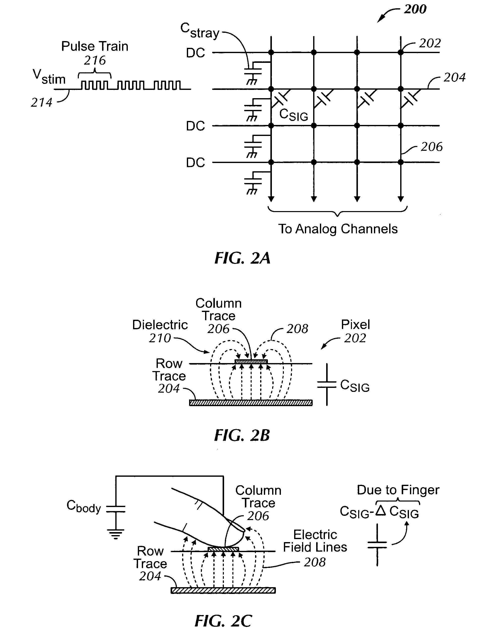
[0024]A plurality of touch sensors in a multi-touch panel can enable a computing system to sense multi-touch events (the touching of fingers or other objects upon a touch-sensitive surface at distinct locations at about the same time) and perform additional functions not previously available with touch sensor devices.

[0025]Although some embodiments may be described herein in terms of capacitive touch sensors in a multi-touch panel, it should be understood that embodiments of the invention are not so limited, but are generally applicable to the use of any type of mult...


PUM


Abstract

An oscillating signal of relatively precise frequency is generated by tuning an oscillator using an external stable oscillating source as a reference. Calibration logic is included to compare a signal from the local oscillator to the reference signal and vary the local signal to a desired frequency. In one embodiment, a binary search algorithm is used to tune the local oscillator. The local oscillating signal can be sent to one or more circuits including at least one sensor of a touch sensitive panel for detecting touch events.

Description

FIELD OF THE INVENTION[0001]The present invention relates to tuned oscillation circuits for electronic devices, and more particularly to tuning a variable oscillator to produce a precise oscillating signal.BACKGROUND OF THE INVENTION[0002]Many types of input devices are presently available for performing operations in a computing system, such as buttons or keys, mice, trackballs, touch panels, joysticks, touch screens and the like. Touch screens, in particular, are becoming increasingly popular because of their ease and versatility of operation as well as their declining price. Touch screens may include a touch panel, which may be a clear panel with a touch-sensitive surface. The touch panel may be positioned in front of a display screen so that the touch-sensitive surface covers the viewable area of the display screen. Touch screens may allow a user to make selections and move a cursor by simply touching the display screen via a finger or stylus. In general, the touch screen may re...

Claims


Application Information

Patent Timeline
Patent Type & Authority Patents(United States)
IPC IPC(8): G09G5/00
CPCG06F3/0418G06F3/044G06F3/0446G06F3/04184
Inventor WILSON, THOMAS JAMES
Owner APPLE INC
Learn More