
Method and apparatus for optimizing synchronous switching operations in power systems

a technology of synchronous switching and power system, applied in the field of methods, can solve the problems of reducing switching transients, excessive stress on power system equipment, and still occurring switching transients

Inactive Publication Date: 2011-12-27
ABB (SCHWEIZ) AG
View PDF3 Cites 6 Cited by
  • Summary
  • Abstract
  • Description
  • Claims
  • Application Information

AI Technical Summary

Benefits of technology

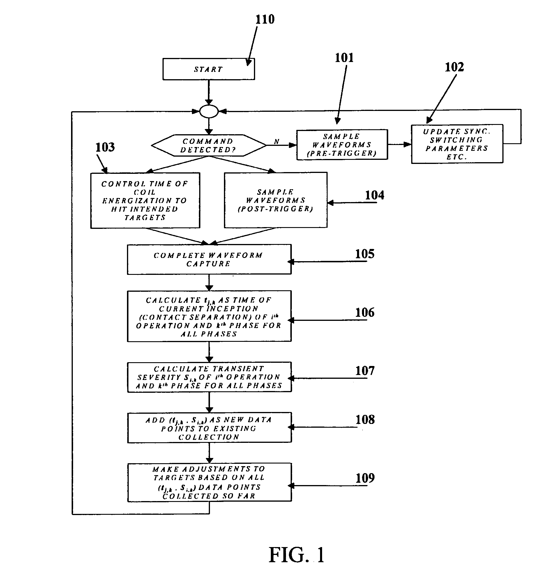
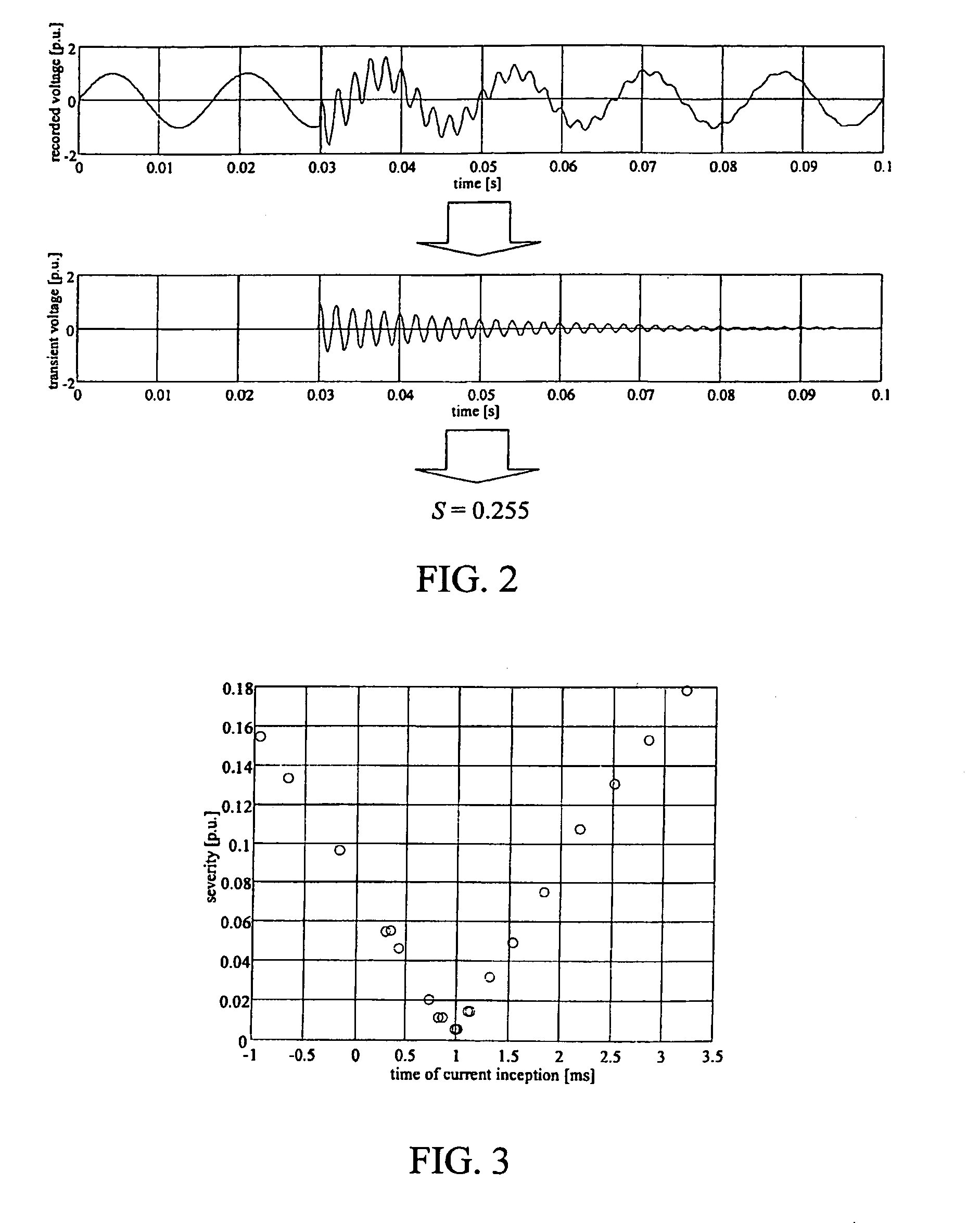
The present invention provides a method for optimizing switching operations executed by a switching device operatively coupled to an AC power line. The method involves acquiring signals related to the waveform of the electrical phases of the AC power line, storing the signals for a predetermined period of time, calculating first data indicative of the time occurred for the executed switching operation, and based on the signals stored, calculating second data indicative of the severity of switching transients occurred during the executed switching operation. The second data is used to determine if a predefined parameter representative of a target point on the waveform for executing future switching operations substantially synchronous with the current waveform needs to be adjusted. The invention also provides an electronic device and a computer readable medium for performing the method. The technical effect of the invention is to improve the efficiency and reliability of switching operations executed by the switching device.

Problems solved by technology

These concerns include both power quality issues for voltage-sensitive customer loads, and excessive stresses on power system equipment.
However, in spite of theoretical knowledge and system studies performed to identify the targets on the voltage (or current) AC waveform for each pole to close (or open) that will result in the desired reduction of switching transients, some switching transients may still occur due to deviations of the theoretical behavior of the system from its practical behavior.

Method used


Image

  • Method and apparatus for optimizing synchronous switching operations in power systems
  • Method and apparatus for optimizing synchronous switching operations in power systems
  • Method and apparatus for optimizing synchronous switching operations in power systems

Examples


Embodiment Construction

[0048]It should be noted that in the detailed description that follows, identical components have the same reference numerals, regardless of whether they are shown in different embodiments of the present invention. It should also be noted that in order to clearly and concisely disclose the present invention, the drawings may not necessarily be to scale and certain features of the invention may be shown in somewhat schematic form.

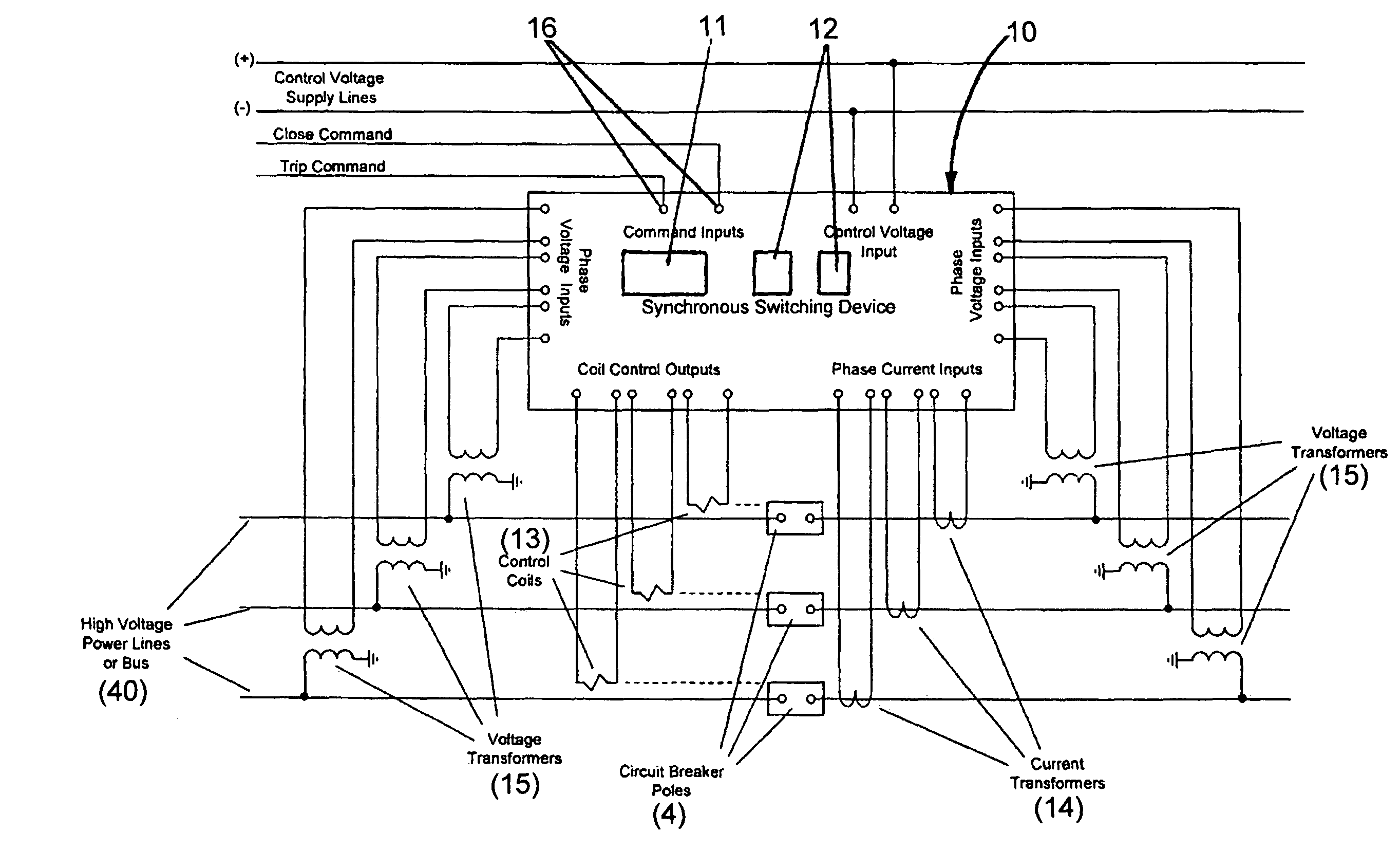
[0049]FIG. 4 schematically illustrates an exemplary embodiment of a power system according to the present invention comprising a high-voltage apparatus indicated by the overall reference number 100. The apparatus 100 comprises a high-voltage switchgear 1 which is suitable to be operatively coupled to an associated AC power line 40, typically a three-phase AC power line. In the exemplary embodiment of FIG. 4 there is illustrated only one pole of the switchgear 1 which is coupled to a corresponding phase of the power line 40. It is to be understood that the pr...


PUM


Abstract

A method and an apparatus for optimizing switching operations executed by a switching device coupled to an AC power line, wherein signals related to the waveform of the electrical phases of the power line are acquired. When a command for executing a switching operation on one of the electrical phases is issued, the signals acquired are stored. Based on the signals stored, data indicative of the severity of switching transients occurred during the executed switching operation and second data indicative of the time occurred for the executed switching operation are calculated and correlated to each other. Based on the data calculated, it is determined whether a parameter representative of a target point on the waveform for executing future switching operations substantially synchronous with the waveform has to be adjusted.

Description

CROSS REFERENCE TO RELATED APPLICATIONS[0001]This application claims the priority of U.S. provisional patent application Ser. No. 60 / 972,263 filed on Sep. 14, 2007, entitled “Method and Apparatus for Optimizing Synchronous Switching Operations in Power Systems” the contents of which are relied upon and incorporated herein by reference in their entirety, and the benefit of priority under 35 U.S.C. 119(e) is hereby claimed.BACKGROUND OF THE INVENTION[0002]This invention relates in general to the field of synchronous switching operations in power lines. In particular, the present invention relates to a method and an apparatus for optimizing synchronous switching operations executed by a switching device operatively coupled to an AC power line.[0003]As it is well known, power systems for transmitting and distributing electricity from power sources to various loads and users are equipped with several types of protecting switchgear, such as high-voltage circuit breakers. Such switchgear a...

Claims


Application Information

Patent Timeline
Patent Type & Authority Patents(United States)
IPC IPC(8): H01H47/00H01H83/00
CPCH01H9/563H03K17/133
Inventor POELTL, ANTONMENDIK, MICHAEL
Owner ABB (SCHWEIZ) AG
Learn More