
Missile system using two-color missile-signature simulation using mid-infrared test source semiconductor lasers

Active Publication Date: 2011-12-27
LOCKHEED MARTIN CORP
View PDF18 Cites 11 Cited by
  • Summary
  • Abstract
  • Description
  • Claims
  • Application Information

AI Technical Summary

Benefits of technology

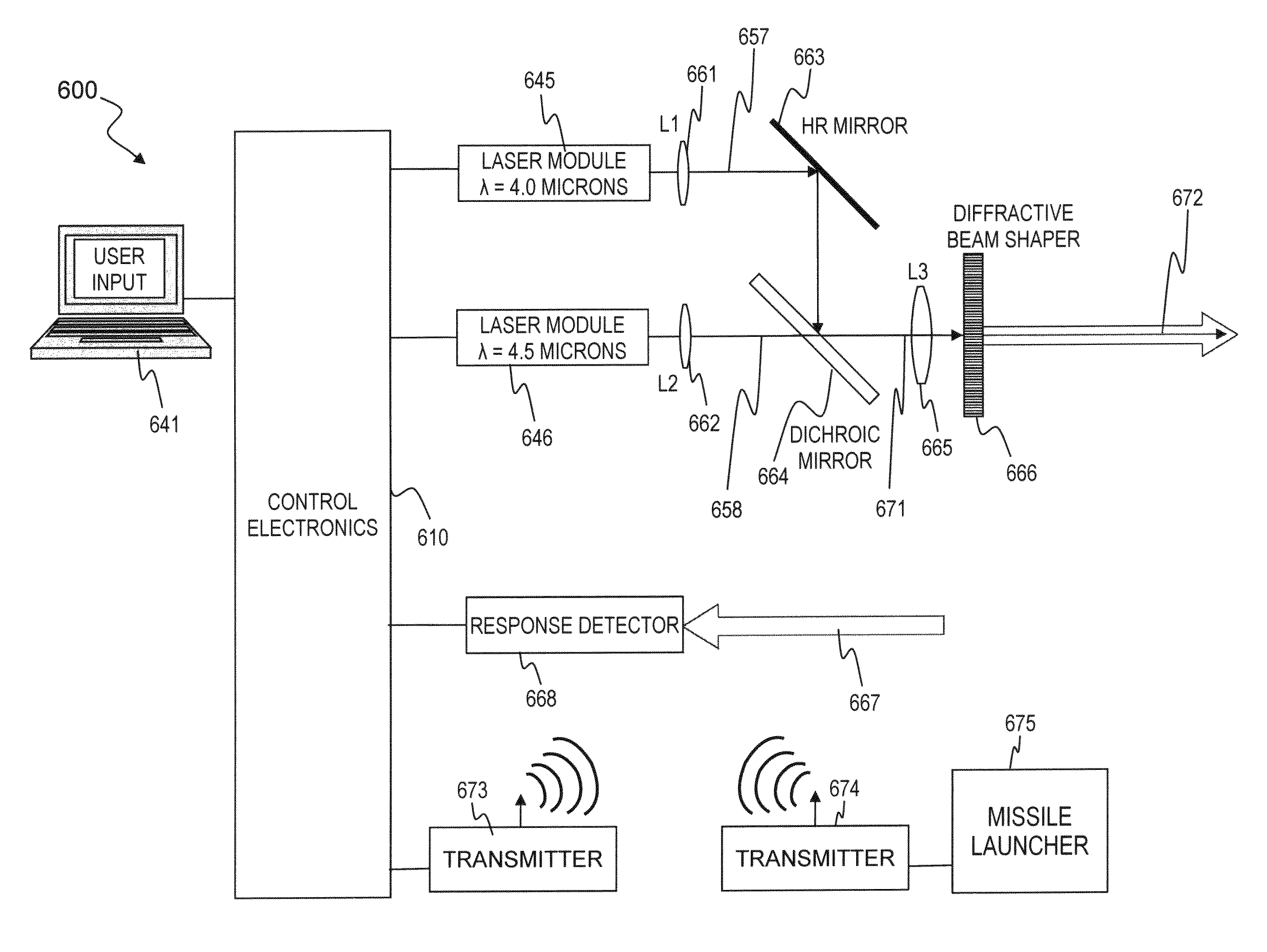
[0010]In some embodiments, the present invention provides an apparatus and process that output a plurality of optical signals (e.g., in the 4.0 and 4.6 micron-wavelength bands, in some embodiments) to simulate one or more missiles, in order to spoof and counter a hostile aircraft's missile warning system(s) and anti-missile countermeasures in order that an anti-aircraft missile can be launched effectively without being disabled by the hostile aircraft's countermeasures) and can be implemented, for example, on a naval vessel for defending against hostile aircraft, by distracting, exhausting, confusing, overwhelming, or bypassing the hostile aircraft's anti-missile defenses so that the naval vessel's anti-aircraft defensive missiles can be launched effectively to shoot down or disable the hostile aircraft. The present invention can also be implemented on a land-based installation to defend against hostile aircraft (airplanes, helicopters or missiles), or on aircraft to defend against other aircraft.

Problems solved by technology

Such systems are complex and expensive, and can be difficult to test on a regular basis.

Method used


Image

  • Missile system using two-color missile-signature simulation using mid-infrared test source semiconductor lasers
  • Missile system using two-color missile-signature simulation using mid-infrared test source semiconductor lasers
  • Missile system using two-color missile-signature simulation using mid-infrared test source semiconductor lasers

Examples


Embodiment Construction

[0023]Although the following detailed description contains many specifics for the purpose of illustration, a person of ordinary skill in the art will appreciate that many variations and alterations to the following details are within the scope of the invention. Accordingly, the following preferred embodiments of the invention are set forth without any loss of generality to, and without imposing limitations upon the claimed invention.

[0024]In the following detailed description of the preferred embodiments, reference is made to the accompanying drawings that form a part hereof, and in which are shown by way of illustration specific embodiments in which the invention may be practiced. It is understood that other embodiments may be utilized and structural changes may be made without departing from the scope of the present invention.

[0025]The leading digit(s) of reference numbers appearing in the Figures generally corresponds to the Figure number in which that component is first introduc...


PUM


Abstract

In some embodiments, the present invention provides an apparatus and process that includes control electronics that generate an electronic control signal; and a plurality of optically or electrically pumped semiconductor lasers, quantum-cascade lasers, optical parametric generators, or optical parametric oscillators, operatively coupled to the control electronics, that output an optical signal having a plurality of wavelengths, each wavelength having an output intensity that is varied over time to simulate a combustion signature of a weapon. In some embodiments, at least two different infrared wavelengths are varied differently with time. Some embodiment are implemented as part of, for example, a anti-aircraft defense system, wherein incoming aircraft need to be disabled, and the present invention provides a way of distracting, exhausting, confusing, overwhelming, or bypassing the hostile aircraft's anti-missile defenses so that, e.g., a naval vessel's anti-aircraft defensive missiles can be launched effectively to shoot down or disable the hostile aircraft.

Description

CROSS-REFERENCE TO RELATED APPLICATIONS[0001]This invention claims benefit under 35 U.S.C. §119(e) of U.S. Provisional Patent Application No. 60 / 930,358 filed May 14, 2007 and titled “TWO-COLOR MISSILE-SIGNATURE SIMULATION USING SEMICONDUCTOR LASERS (Mid-infrared test source),” and of U.S. Provisional Patent Application No. 60 / 931,322 filed May 15, 2007 and titled “TWO-COLOR MISSILE-SIGNATURE SIMULATION USING MID-INFRARED TEST SOURCE SEMICONDUCTOR LASERS,” each of which is incorporated herein by reference in its entirety.[0002]This invention is related toU.S. Provisional Patent Application No. 60 / 699,894 titled “APPARATUS AND METHOD FOR GENERATING CONTROLLED-LINEWIDTH LASER-SEED-SIGNALS FOR HIGH-POWERED FIBER-LASER AMPLIFIER” filed Jul. 15, 2005,U.S. patent application Ser. No. 11 / 488,910 titled “APPARATUS AND METHOD FOR GENERATING CONTROLLED-LINEWIDTH LASER-SEED-SIGNALS FOR HIGH-POWERED FIBER-LASER AMPLIFIER SYSTEMS” filed Jul. 17, 2006 (which issued as U.S. Pat. No. 7,539,231 on M...

Claims


Application Information

Patent Timeline
IPC IPC(8): F41J2/02
CPCF41H11/02F42B5/15F42B12/46H04B10/25F41H13/0056G01S7/495
Inventor TIDWELL, STEVEN C.LEMAIRE, CHARLES A.
Owner LOCKHEED MARTIN CORP
Learn More