Apparatus and methods of transferring heat with a differential magneto-thermal force

a technology of differential magneto-thermal force and apparatus, applied in the field of apparatus and methods of transferring heat with a differential magnetothermal force, can solve the problems of energy waste and unaddressed need in the art, and achieve the effect of improving the efficiency of the engin

Active Publication Date: 2011-12-27
LUO WEILI
View PDF8 Cites 0 Cited by
  • Summary
  • Abstract
  • Description
  • Claims
  • Application Information

AI Technical Summary

Benefits of technology

[0007]When one carefully studies the set up as shown in FIG. 1, there is no fundamental reason why one can not find a mechanism to use the same heat reservoir as both high and low temperature sources. The first aspect of the present invention relates to a mechanism to transfer externally deposited heat (or cold) from cold to hot side (or from hot to cold side) in a fluid with a magnetic force (note that, in the absent of magnetic field, heat deposited to a system with temperature gradient tends to propagate to the cold side due to thermal conduction), which leads to the maximum possible temperature gradient in the system. This mechanism renders the possibility of a new generation of single-heat-source engines by bringing the “waste heat” from the working device back to the heat reservoir, in any orientation regardless the direction of gravity, thus to recycle the output energy from the engine at our convenience and to improve the efficiency of the engine to nearly 100%, much larger than that of existing engines.
[0009]To take the maximum advantage of this invention, “free” energies from nature, such as solar energy or energies from other heat-releasing devices such as air conditioners and refrigerators, can be utilized to increase the power generated from this engine. The principle of this invention can be applied to the electric counterpart of a magnetically driven engine since the theory is symmetrical for both magnetic and electric forces. For optimum performance, paramagnetic salts or magnetic particles can be added to enhance the susceptibility of the fluid.

Problems solved by technology

For conventional technologies, the heat-transferring medium can be recycled while the heat energy output at the low temperature reservoir 120, Q2, is discarded outside, resulting in energy waste.
Therefore, a heretofore unaddressed need exists in the art to address the aforementioned deficiencies and inadequacies.

Method used


Image

  • Apparatus and methods of transferring heat with a differential magneto-thermal force
  • Apparatus and methods of transferring heat with a differential magneto-thermal force
  • Apparatus and methods of transferring heat with a differential magneto-thermal force

Examples


examples and implementations

[0073]Without intent to limit the scope of the invention, further exemplary methods and their related results according to the embodiments of the present invention are given below. Note again that titles or subtitles may be used in the examples for convenience of a reader, which in no way should limit the scope of the invention. Moreover, certain theories are proposed and disclosed herein; however, in no way they, whether they are right or wrong, should limit the scope of the invention.

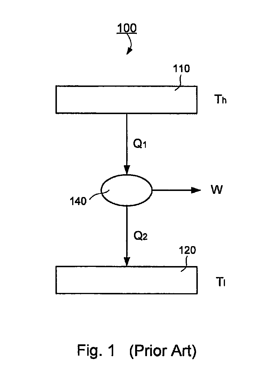
[0074]FIG. 1 illustrates typical working principle in the existing technology of a general engine based on Carnot cycle. The high temperature heat source at temperature Th provide heat Q1 to do work, W, to outside. In this technology, amount of heat Q2 cannot be converted to work and has to be deposited to the low temperature source Tl. In most cases, the heat was released to the environment as in steam engines, car engines, combustion engines, and all other modern engines, as well as all power genera...


PUM


Abstract

A method of heat energy transfer, hi one embodiment, the method comprises the steps of establishing a temperature gradient along a first direction in a heat reservoir with a medium and having a first end portion and an opposite, second end portion defining a length, L, therebetween, wherein the first direction is from the first end portion to the second end portion, such that the first end portion has a first temperature, Ti1; and the second end portion has a second temperature, Ti<Tj1; and applying an electromagnetic field in the heat reservoir to establish an electromagnetic field gradient along a second direction to generate a driving force to transfer heat energy from the second end portion to the first end portion.

Description

CROSS-REFERENCE TO RELATED PATENT APPLICATION[0001]This application claims the benefit, pursuant to 35 U.S.C. §119(e), of U.S. provisional patent application Ser. No. 60 / 692,460, filed Jun. 21, 2005, entitled “Differential Magneto-Thermal Single-Heat-Source Engine,” by Weili Luo, which is incorporated herein by reference in its entirety.[0002]Some references, which may include patents, patent applications and various publications, are cited in a reference list and discussed in the description of this invention. The citation and / or discussion of such references is provided merely to clarify the description of the present invention and is not an admission that any such reference is “prior art” to the invention described herein. All references cited and discussed in this specification are incorporated herein by reference in their entireties and to the same extent as if each reference was individually incorporated by reference. In terms of notation, hereinafter, “[n]” represents the nth...

Claims


Application Information

Patent Timeline
Patent Type & Authority Patents(United States)
IPC IPC(8): F25B21/00
CPCF25B21/00F25B2321/0021F25B2321/0022Y02B30/66Y02B30/00
Inventor LUO, WEILI
Owner LUO WEILI
Why Eureka
Try Eureka