
Displaying signals of a design block emulated in hardware co-simulation

a technology of hardware cosimulation and display signals, applied in the field of hardware cosimulation of electronic systems, can solve the problem of time-consuming and laborious problems of verifying the correct behavior of electronic systems

Active Publication Date: 2011-12-20
XILINX INC
View PDF7 Cites 7 Cited by
  • Summary
  • Abstract
  • Description
  • Claims
  • Application Information

AI Technical Summary

Problems solved by technology

However, verifying correct behavior of the electronic system may be time-consuming because the encapsulation of the design block in the hardware-based co-simulation platform may prevent accessing the internal signals of the design block.

Method used


Image

  • Displaying signals of a design block emulated in hardware co-simulation
  • Displaying signals of a design block emulated in hardware co-simulation
  • Displaying signals of a design block emulated in hardware co-simulation

Examples


Embodiment Construction

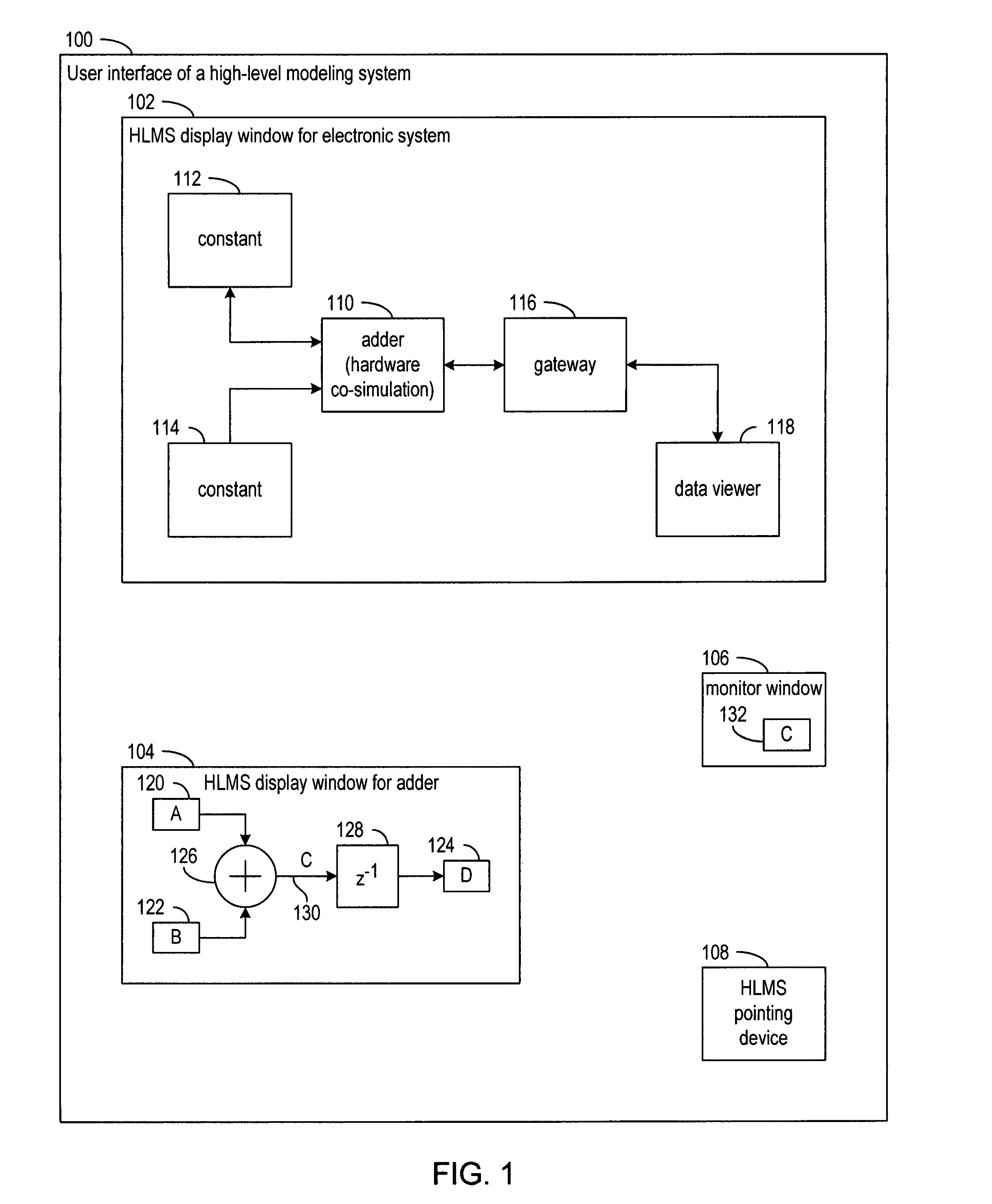
[0018]FIG. 1 is a block diagram of a user interface 100 of a high-level modeling system (HLMS) for an example electronic system in accordance with various embodiments of the invention. The user interface 100 may have one or more displays that display windows 102, 104, and 106 for illustrating various aspects of the example electronic system. The user interface 100 may also include a pointing device 108, such as a mouse, for manipulating the various aspects of the example electronic system illustrated by windows 102, 104, and 106.

[0019]A top level of a hierarchy for the example electronic system may be shown by window 102. The example electronic system may include an adder 110 that adds the values from constant generators 112 and 114. Gateway 116 may convert data types between a fixed-point data type produced by adder 110 and a floating-point data type expected by data viewer 118. Adder 110 may use a fixed-point data type, which may have a precision that is selectable by a user of th...


PUM


Abstract

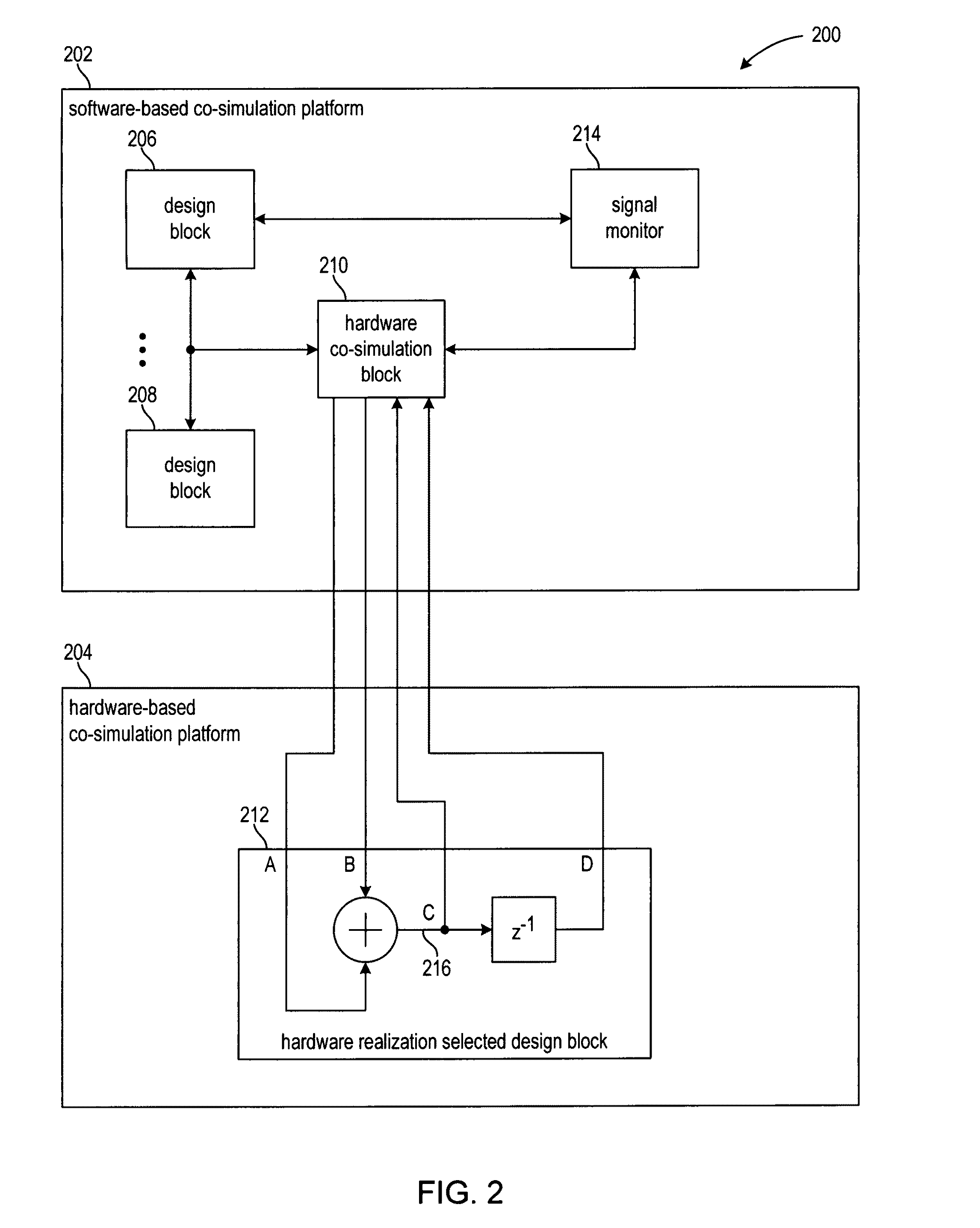
Methods and systems for simulating an electronic system in a high level modeling system (HLMS). A design block and certain signals of the electronic system are selected. The selected signals include internal signals of the design block that are not ports of the design block. The electronic system is simulated in the HLMS, which includes a hardware-based co-simulation platform and a software-based co-simulation platform. A hardware realization of the design block is automatically generated and the design block is emulated in the hardware based co-simulation platform using the hardware realization of the design block. A sequence of values is displayed for the selected signals of the electronic system. During the simulation of the electronic system in the HLMS, the sequence of values for the internal signals of the design block and another sequence of values for the ports of the design block are transferred between the co-simulation platforms.

Description

FIELD OF THE INVENTION[0001]The present invention generally relates to simulation of electronic systems, and more particularly to hardware co-simulation of electronic systems.BACKGROUND[0002]During the process of developing an electronic system, the behavior of the electronic system may be simulated based on a specification of the design of the electronic system. Simulating the electronic system helps to verify correct behavior prior to physical implementation of a circuit for the electronic system. Wasted manufacturing costs due to faulty design may thereby be avoided.[0003]Numerous tools are available for simulating electronic systems including, for example, high-level modeling systems (HLMSs). Co-simulation may also be used when the design may be more efficiently simulated by simulating different parts of the design on different simulation platforms (“co-simulation platforms”).[0004]Example co-simulation platforms include both software-based and hardware-based platforms. In a sof...

Claims


Application Information

Patent Timeline
Patent Type & Authority Patents(United States)
IPC IPC(8): G06F17/50
CPCG06F17/5027G06F2217/86G06F30/331G06F2117/08
Inventor BALLAGH, JONATHAN B.HIRSCH, MICHAEL D.
Owner XILINX INC
Learn More