
Bonding fastener assembly for electrical grounding

a technology of electrical grounding and fasteners, which is applied in the direction of securing devices, pins, washers, etc., can solve the problems of affecting the appearance of components, time-consuming and error-prone grounding wire attachment, and insufficient direct attachment using conventional nuts and bolts to provide electrical connections

Active Publication Date: 2011-12-06
LEGRAND AV INC
View PDF13 Cites 46 Cited by
  • Summary
  • Abstract
  • Description
  • Claims
  • Application Information

AI Technical Summary

Problems solved by technology

Since many racks have a protective paint coating, the direct attachment using conventional nuts and bolts is not, in some cases, sufficient to provide an electrical connection.
While this type of attachment is adequate for providing electrical grounding, the attachment of the grounding wires is time consuming and subject to error should the ground connection not be properly completed.
While the Panduit product does address the problem for breaking through the paint layer to reach the base metal, Applicant has determined that the product negatively impacts the appearance of the components and can create a corrosion source since the serrations are designed to remove a complete circular ring of paint exposing the bare metal.
The ring of bare metal is susceptible to corrosion unless an anti-oxidant is applied.
However, application of anti-oxidants is an additional assembly step and can be difficult to apply.

Method used


Image

  • Bonding fastener assembly for electrical grounding
  • Bonding fastener assembly for electrical grounding
  • Bonding fastener assembly for electrical grounding

Examples


Embodiment Construction

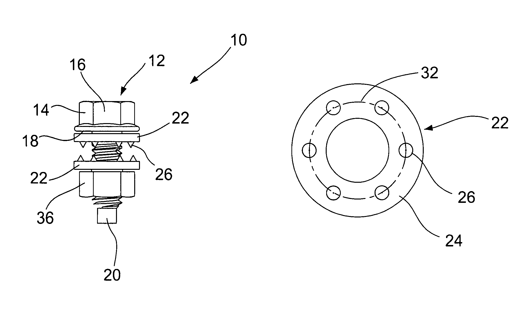
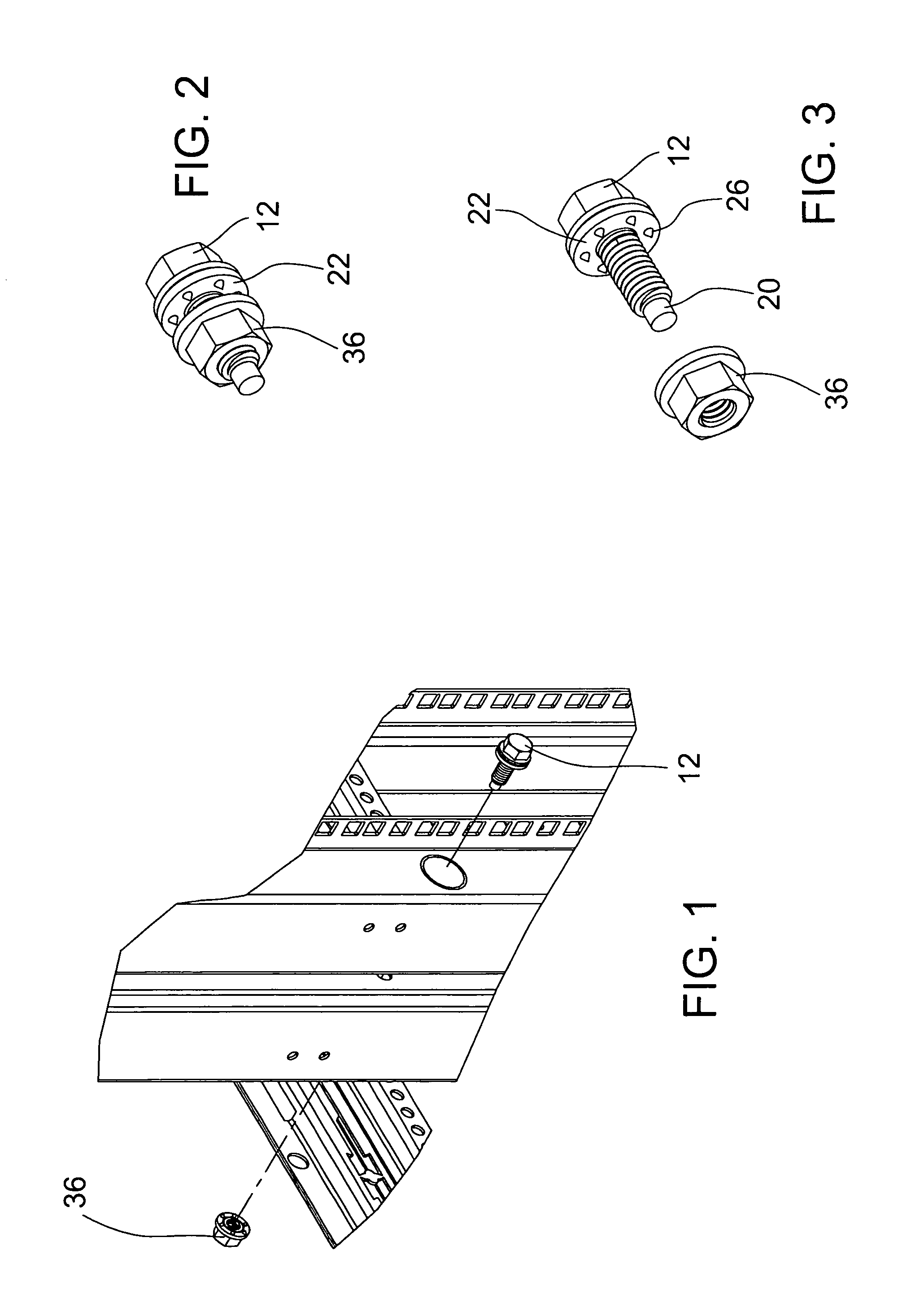
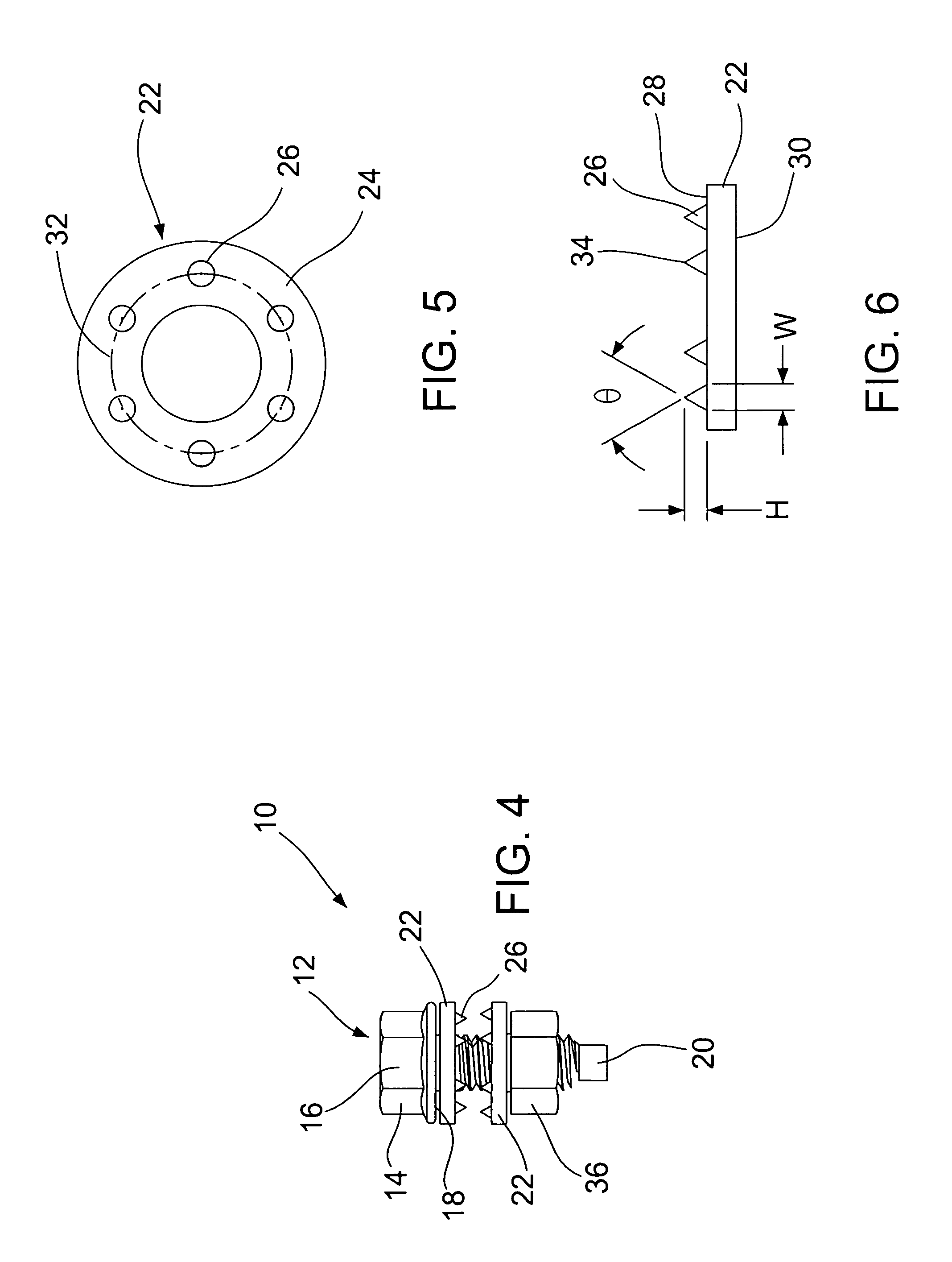
[0020]FIG. 1 illustrates one embodiment of the bonding fastener assembly 10 of the present invention as it is contemplated for use in attaching two rack assemblies. As shown in FIGS. 1-3, the bonding fastener assembly 10 includes a fastener 12 with a head 14, including a top surface 16 and bottom surface 18, a shaft 20 and a spiked washer 22. The top surface 16 of the head 14 has a conventional configuration designed to be engaged with a common installation tool. For example, the head may include a recess for receiving a Phillips head screwdriver, or may have a polygonal shape for engagement with a suitable ratchet. The various configurations that the top surface can be formed in are well known to those skilled in the art and, therefore, no further discussion is needed. The bottom surface 18 of the head 14 is preferably flat. The shaft 20 is integral with the head 14 and extends from the second surface. The shaft 20 includes threads on at least a portion of its surface for engagemen...


PUM


Abstract

A fastener assembly comprising a fastener with a head having a first surface and second surface, and a shaft extending from the second surface of the head. An annular washer is rotatably disposed about the shaft and rotatable relative to the second surface of the fastener head. The washer has an inner diameter, an outer diameter, a first surface and a second, the first surface being positioned adjacent to the second surface of the head. A plurality of identical conical projections extend out from the second surface of the washer and are formed integrally therewith.

Description

RELATED APPLICATION[0001]This application is related to and claims priority from U.S. Provisional Application No. 61 / 198,540, filed on Nov. 6, 2008, which is incorporated herein by reference in its entirety.FIELD OF THE INVENTION[0002]The present invention relates to an attachment or fastening system for use in securing two or more structures and, more particularly, to a fastening system for providing electrical conductivity through the secured structures after attachment.BACKGROUND[0003]There are a number of fasteners on the market for securing multiple structures together. In certain structural connections, however, it is important to provide an electrical connection or bond between the structures. This is particularly important in situations were a grounded condition is needed.[0004]For example, in equipment enclosure racks, such as audio or computer equipment racks, grounding through multiple racks is generally required. Since many racks have a protective paint coating, the dire...

Claims


Application Information

Patent Timeline
Patent Type & Authority Patents(United States)
IPC IPC(8): F16B33/00
CPCF16B39/282F16B41/002F16B2001/0064F16B2200/93
Inventor SCHLUTER, ROBERT
Owner LEGRAND AV INC
Learn More