
Spider having spider arms with open channel

a technology of spider arms and open channels, applied in the field of spider arms with open channels, can solve problems such as creating very large loads

Active Publication Date: 2011-12-06
METSO OUTOTEC USA INC
View PDF19 Cites 28 Cited by
  • Summary
  • Abstract
  • Description
  • Claims
  • Application Information

AI Technical Summary

Benefits of technology

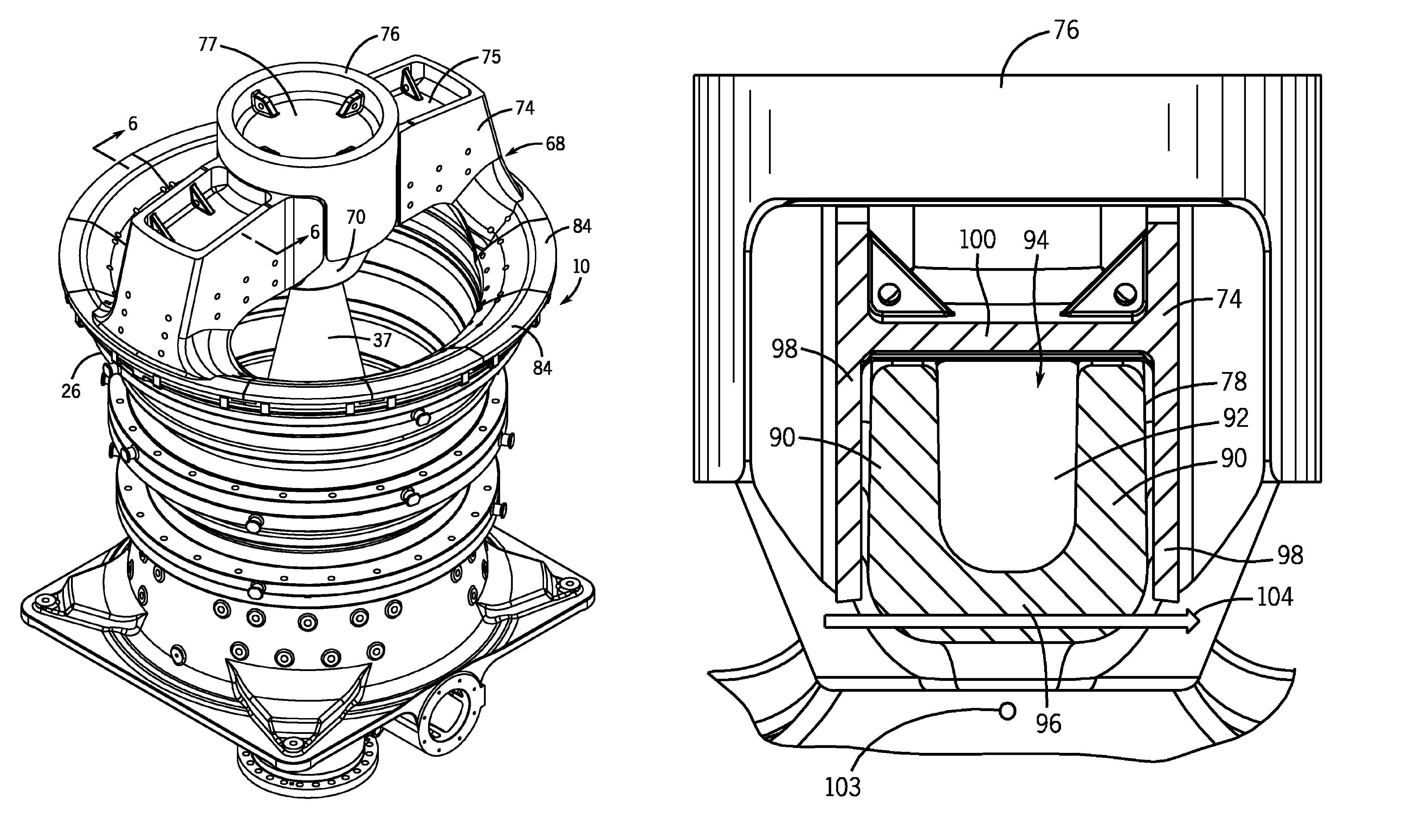
"The present disclosure is about a gyratory crusher that has a spider for breaking rock, stone, or other materials. The spider has a central hub and bushing that receives one end of a gyrating mainshaft. The spider arms are fitted with shields to protect them during use. Each spider arm is formed from a pair of vertically oriented flanges with an underlying web to define a channel. The spider arms form a connecting beam between the central hub and the outer rim of the spider. The spider arms have a shear center typically below the connecting web of the beam, which reduces damaging torsional stresses. The technical effect of this design is to minimize damage to the spider during use."

Problems solved by technology

The crushing forces generated in the crushing cavity create very large loads that are imposed in part on the spider.

Method used


Image

  • Spider having spider arms with open channel
  • Spider having spider arms with open channel
  • Spider having spider arms with open channel

Examples


Embodiment Construction

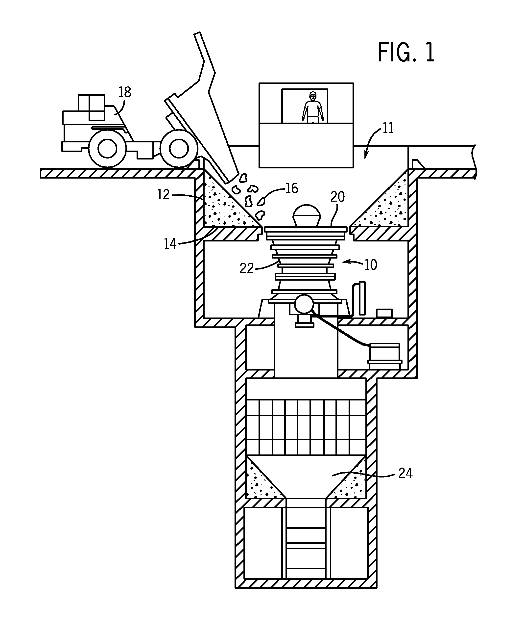
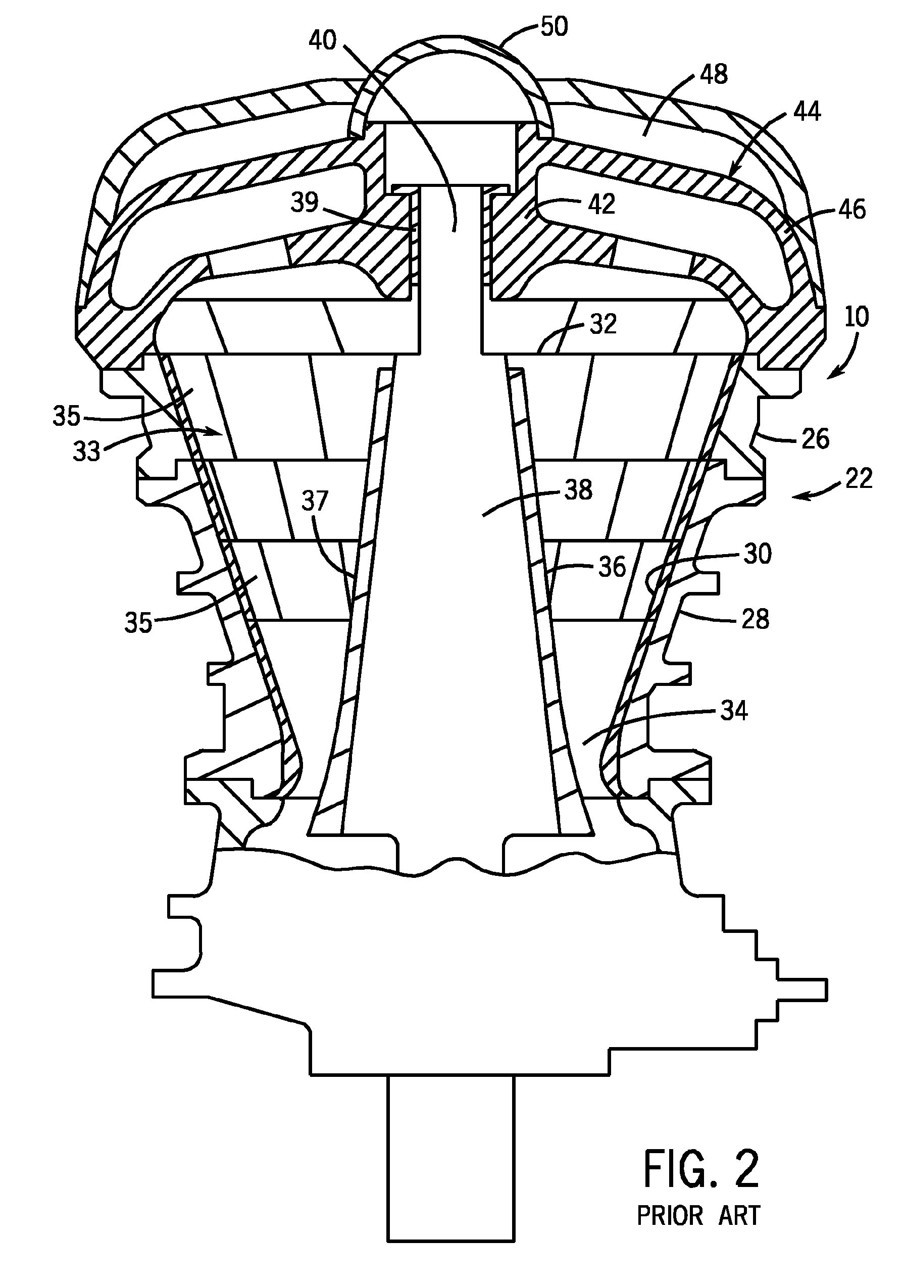
[0017]FIG. 1 illustrates the general use of a rock crushing system 11. As illustrated in FIG. 1, a gyratory rock crusher 10 is typically positioned within a pit 12 having a bottom wall 14. The pit 12 receives a supply of material 16 to be crushed from various sources, such as a haul truck 18. The material 16 is deposited into the pit 12 and is directed toward the top of a crushing cavity positioned below the upper feed end 20 of the rock crusher 10. The material 16 enters the crushing cavity and passes through the concave assembly positioned along the stationary shell assembly 22. Within the shell assembly, a crushing mantle (not shown) gyrates and crushes the material within the crushing cavity. The crushed material exits the gyratory rock crusher 10 and enters into a receiving chamber 24 where the crushed material is then directed away from the rock crushing system 11, such as through a conveyor assembly or other transportation mechanisms. The operation of the rock crushing system...


PUM


Abstract

A spider for use with a gyratory crusher. The spider includes spider arms each formed from two spaced flanges joined by a connecting web to define an open channel having an open top end. The configuration of the spider arms increases manufacturability and provides the required strength and rigidity for the spider. The channel formed in each spider arm is covered by a spider arm shield to reduce abrasive wear to the spider arm.

Description

BACKGROUND OF THE INVENTION[0001]The present disclosure generally relates to a rock crushing machine, such as a rock crusher of configurations commonly referred to as gyratory or cone crushers. More specifically, the present disclosure relates to a spider for use in a gyratory crusher or cone crusher including multiple spider arms each including an open channel formed between two spaced flanges.[0002]Rock crushing machines break apart rock, stone or other materials in a crushing cavity formed between a downwardly expanding conical mantle installed on a mainshaft that gyrates within an outer upwardly expanding frustoconically shaped assembly of concaves inside a crusher shell assembly. The conical mantle and the mainshaft are circularly symmetric about an axis that is inclined with respect to the vertical shell assembly axis. These axes intersect near the top of the rock crusher. The inclined axis is driven circularly about the vertical axis thereby imparting a gyrational motion to t...

Claims


Application Information

Patent Timeline
Patent Type & Authority Patents(United States)
IPC IPC(8): B02C2/06
CPCB02C2/04B02C2/06
Inventor BIGGIN, DAVID FRANCISMARKS, WALTER RAY
Owner METSO OUTOTEC USA INC
Learn More