Apparatus and method for fabricating glass bodies using an aerosol delivery system

a technology of aerosol delivery system and apparatus, which is applied in the field of apparatus and methods for fabricating rare earth (re)doped optical fibers, can solve the problems of low vapor pressure (lvp), inability to deliver using conventional vapor-phase approaches such as standard mcvd, and all have significant limitations

Active Publication Date: 2011-12-06
FURAKAWA ELECTRIC NORTH AMERICA INC
View PDF15 Cites 10 Cited by
  • Summary
  • Abstract
  • Description
  • Claims
  • Application Information

AI Technical Summary

Problems solved by technology

Not all desired dopants can be delivered using this standard MCVD method because appropriate HVP precursors do not exist.
Some desirable dopants such as RE elements [particularly erbium (Er) and ytterbium (Yb)] have low vapor pressure (LVP) precursors and cannot be delivered using conventional vapor-phase approaches, such as standard MCVD.
In an attempt to overcome this problem, several fabrication methods have been developed in the prior art for using LVP RE precursors, but they all have significant limitations.
Solution doping has the following limitations: (i) The reproducibility of the LVP dopant concentration is poor from preform to preform; (ii) The amount of liquid held by the soot layer is dependent on its porosity, which is very difficult to control; and (iii) The process is very time consuming typically taking 1-2 hours per deposited glass layer compared to roughly 10 minutes for a standard MCVD glass layer.
Chelate processes have the following limitation: The chelates contain undesirable elements such as hydrogen and to date have not produced glass with the purity needed for high quality optical fibers.
The ampoule approach has the following limitations: (i) The precursor vapor pressure (and therefore the amount delivered) is very sensitive to temperature, which is difficult to control because an external heat source heats the RE source material, which sits within several concentric glass tubes; (ii) Flowing gas streams cool the tubes, causing uncertainty in the actual source temperature; (iii) Only a small surface area exists between the precursor and the carrier gas, so it is unlikely that the precursor will become saturated in the carrier gas.
If large particles are formed, current wisdom suggests that they will form clusters, which may be detrimental for RE-doped preforms and fibers.
This liquid aerosol approach has the following limitations: (i) The solution is flammable and can lead to explosions; (ii) A new solution needs to be made whenever a different glass composition is desired; (iii) The process is time consuming; and (iv) The process is not expected to produce very low loss glass inasmuch as the reaction products include contaminants such as H2O and H2 as well as the desired glass oxides.

Method used


Image

  • Apparatus and method for fabricating glass bodies using an aerosol delivery system
  • Apparatus and method for fabricating glass bodies using an aerosol delivery system
  • Apparatus and method for fabricating glass bodies using an aerosol delivery system

Examples


example 1

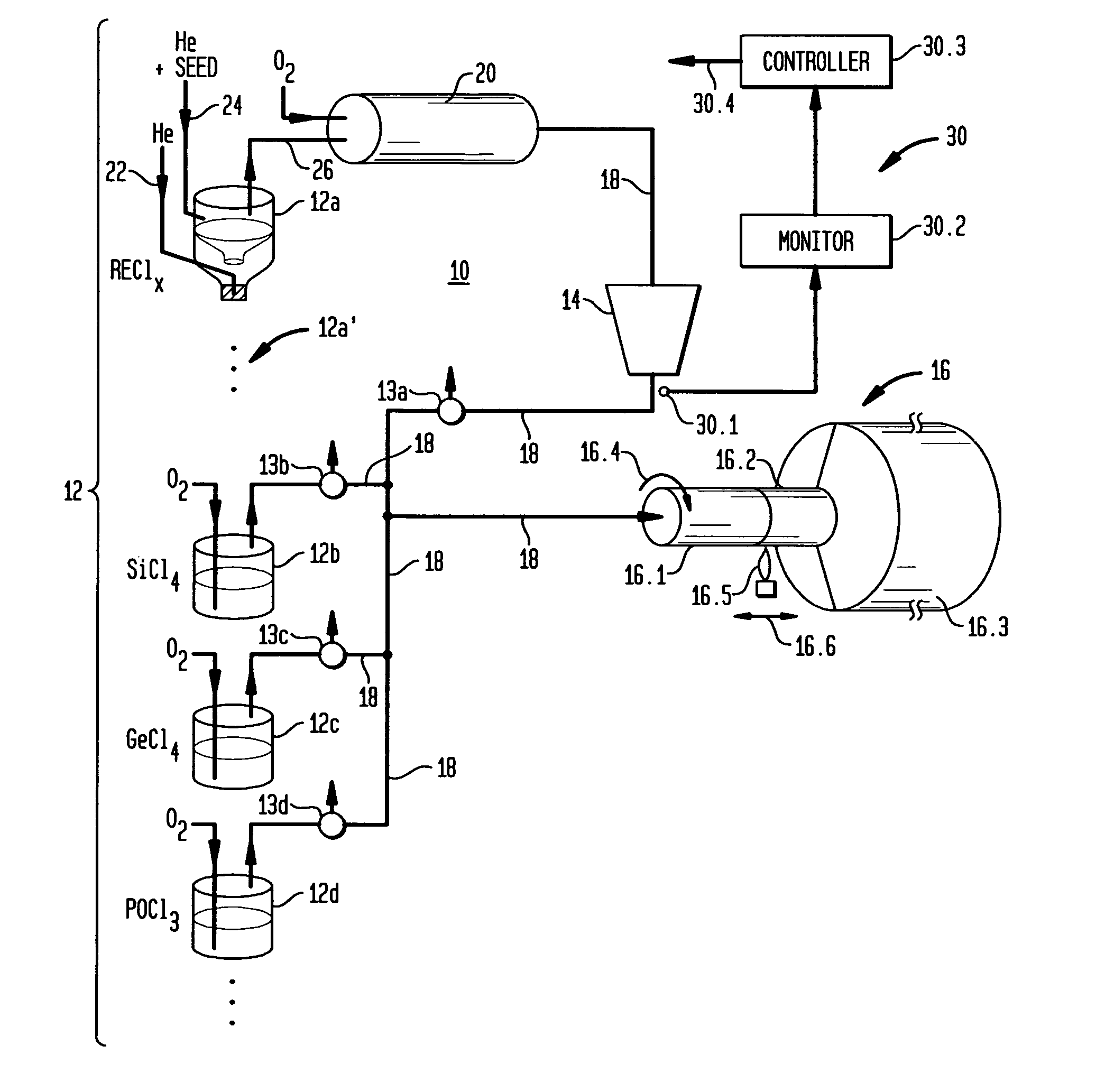
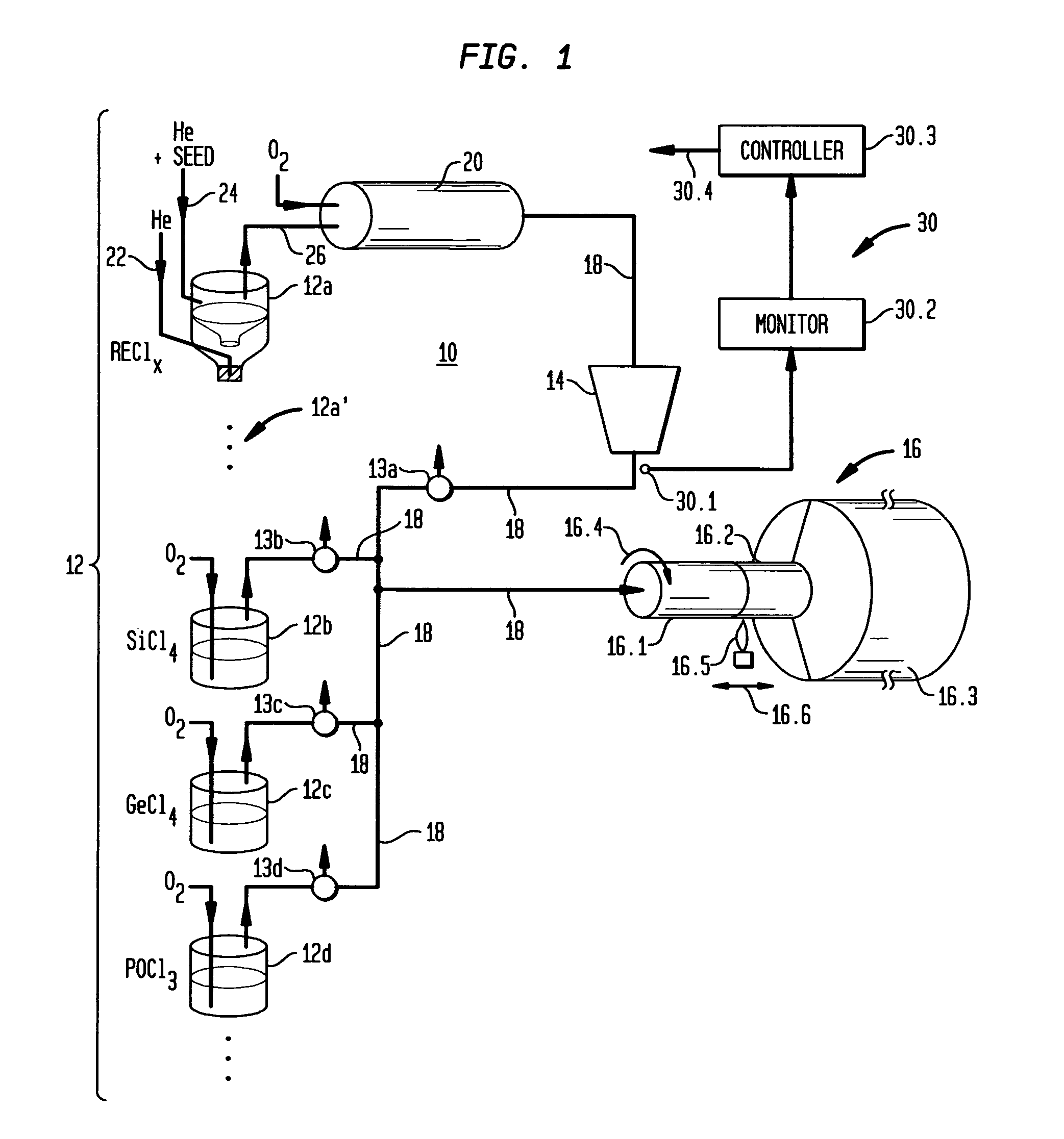
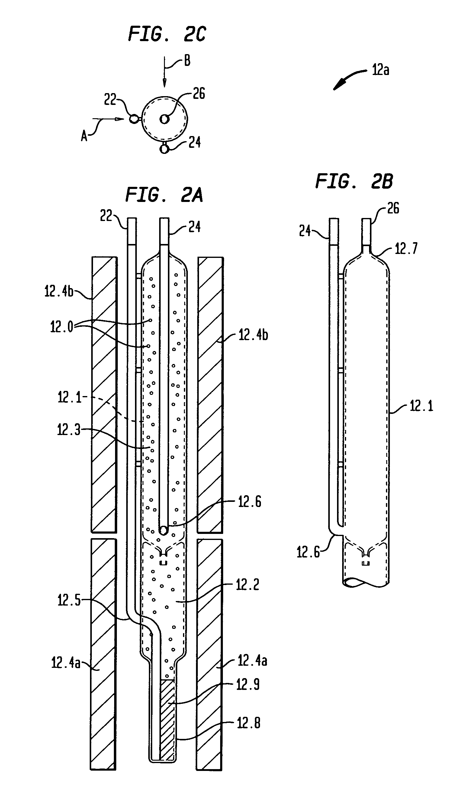
[0063]The first example outlines a Yb—Al-doped silica preform that we fabricated. The YbCl3 aerosol generator 12a was maintained at 975° C. to achieve a high concentration of Yb. The primary He flow that bubbled through the molten YbCl3 was set to 0.5 liters / min, and the secondary He flow that cooled the saturated YbCl3 vapor in the condenser chamber 12.1 was set to 0.3 liters / min. These conditions for the aerosol generator were maintained for 1 hr before delivery to allow the system to reach equilibrium.

[0064]The MCVD system 16 was set up in the usual fashion, and all steps prior to the deposition of the Yb—Al-doped silica soot layers were carried out with the aerosol three-way valve 13a set to vent and using standard MCVD techniques. For deposition of the Yb—Al-doped layers, the valve 13a was switched so that the aerosol entered the delivery tube and mixed with the other precursor and process gases (e.g., He, O2). The SiCl4 bubbler 12b was maintained at 38° C. 100 sccm of O2 was b...

example 2

[0066]The second example outlines the fabrication of another Yb—Al-doped silica preform, as well as a fiber we drew from it. The aerosol generator 12a was maintained at 950° C. The primary He flow that bubbled through the molten YbCl3 was set to 0.38 liters / min and the secondary He flow that cooled the saturated YbCl3 vapor in the condenser chamber 12.1 was set to 0.5 liters / min. These conditions for the aerosol generator were maintained for 1 hr before delivery to allow the system to reach equilibrium.

[0067]The MCVD system 16 was set up in the usual fashion and all steps prior to the deposition of the Yb—Al-doped silica were carried out with the aerosol three-way valve 13a set to vent using standard MCVD techniques. For deposition of the Yb—Al-doped layers, the valve 13a was switched so that the aerosol entered the delivery tube and mixed with the other precursor and process gases. The SiCl4 bubbler 12b was maintained at 38° C. 100 sccm of O2 was bubbled through the SiCl4 precursor...


PUM

PropertyMeasurementUnit
sizesaaaaaaaaaa
vapor pressureaaaaaaaaaa
temperaturesaaaaaaaaaa

Abstract

A method of fabricating a glass body that includes a multiplicity of constituents, at least one of which is a dopant (e.g., a rare-earth element) having a low vapor pressure (LVP) precursor comprises the steps of: (a) generating an aerosol from the LVP precursor; (b) separately generating vapors of the other constituents; (c) convecting the aerosol and vapors to deposition system including a substrate; and (d) forming at least one doped layer on a surface of the substrate. In one embodiment, the method also includes filtering the aerosol so as to remove aerosol particles outside of a particular range of sizes. Also described is a unique aerosol generator that is particularly useful in generating aerosols of rare-earth dopants. Particular embodiments directed to the fabrication of Yb-doped optical fibers are described.

Description

CROSS REFERENCE TO RELATED APPLICATIONS[0001]This application claims priority from copending, provisional application Ser. No. 60 / 750,966 filed on Dec. 16, 2005 and entitled “Aerosol Delivery Method for Optical Fiber and Fiber Preform Fabrication.”BACKGROUND OF THE INVENTION[0002]1. Field of the Invention[0003]This invention relates to glass bodies (e.g., optical fibers, planar waveguides, glass soot) and, more particularly, to apparatus and methods for fabricating rare-earth (RE)-doped optical fibers.[0004]2. Discussion of the Related Art[0005]In the standard MCVD technique for fabricating optical fibers, preforms are made by flowing relatively high vapor pressure (HVP) precursor gasses (e.g., SiCl4, GeCl4 and POCl3) and oxygen down a rotating silica substrate tube. An external hydrogen-oxygen torch slowly traverses the length of the tube, locally heating a small section of the tube. The gas stream, which moves much faster than the torch, is heated as it approaches the torched sect...

Claims


Application Information

Patent Timeline
Patent Type & Authority Patents(United States)
IPC IPC(8): C03B37/018
CPCC03B19/1438C03B37/01433C03B37/01838B01D1/0005C03B2201/34C03B2201/31C03B2207/81C03B2207/87C03B2201/28C03B2201/36
Inventor DESANTOLO, ANTHONY MICHAELWINDELER, ROBERT SCOTT
Owner FURAKAWA ELECTRIC NORTH AMERICA INC
Why Eureka
Try Eureka