
Luminary

a technology of light source and battery power, applied in the field of light source, can solve the problems of increasing the cost of the luminary, reducing the service life of the light source, and requiring higher power consumption in normal illumination, so as to prevent the power consumption of the battery and the effect of rapid consumption

Inactive Publication Date: 2011-11-29
JIANGMEN MINHUA ELECTRIC
View PDF8 Cites 15 Cited by
  • Summary
  • Abstract
  • Description
  • Claims
  • Application Information

AI Technical Summary

Benefits of technology

"The invention is a luminary that has two light sources with the same emission direction for normal and emergency illumination. It consists of a central lamp, an emergency lamp and a control box. The central lamp is the main light source with a light-emitting end. The emergency lamp is a ring-shaped lamp that surrounds the light-emitting end of the central lamp and has a base and a circuit board. The circuit board is attached to the base and has an LED set and a cable set. The control box is connected to the cable set and has a battery. It drives the LED set when there is no AC power. The emergency lamp emits light in the same direction as the central lamp, ensuring the same lighting arrangement during a blackout. The emergency illumination is independent of the normal illumination provided by the central lamp, preventing the battery power from being quickly consumed by the central lamp. The technical effect of this invention is to provide a reliable and efficient lighting solution for both normal and emergency situations."

Problems solved by technology

However, normal illumination usually requires higher power consumption as compared with emergency illumination.
Since the conventional luminary uses the same light source for both normal and emergency illumination, the light source is designed with large power requirements.
Therefore the battery of the luminary needs larger capacity to provide electricity to the light source to keep a sufficient time for emergency illumination and increases cost of the luminary.

Method used


Image

  • Luminary
  • Luminary
  • Luminary

Examples


Embodiment Construction

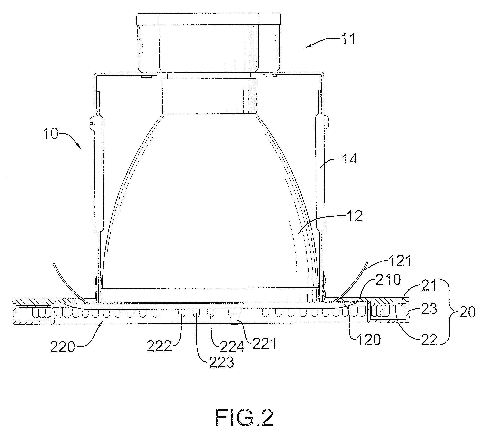
[0023]With reference to FIG. 1, a luminary in accordance with the present invention comprises a central lamp (10), an emergency lamp (20) and a control box (30).

[0024]The central lamp (10) has a light-emitting end and may have a socket (11), a shade (12), a light emitting element (13) and a frame (14). The shade (12) is attached to the socket (11) and has a front open end and may have a circular flange (120) and multiple reeds (121). The circular flange (120) is formed on and protrudes from the front open end. The reeds (121) are mounted on the front open end, adjacent to the circular flange (120) and are elastic. The light emitting element (13) is mounted on the socket (11) in the shade (12). The frame (14) is fixed to the socket (11) and the shade (12).

[0025]The emergency lamp (20) is ring-shaped, mounted around the light-emitting end of the central lamp (10) and has a base (21), a circuit board (22) and may have a cover (23).

[0026]With further reference to FIG. 2, the base (21) i...


PUM


Abstract

A luminary has a central lamp, an emergency lamp and a control box. The emergency lamp is ring-shaped and mounted around a light-emitting end of the central lamp and has a base and a circuit board. The circuit board has an LED set and a cable set connected to the LED set. The control box is electrically connected to cable set of the circuit board, adapted to connect to an AC power and has a battery. The control box drives the LED set when an outage of the AC power occurs. Since emergency illumination is provided by the emergency lamp and is independent of normal illumination provided by the central lamp, battery power for emergency illumination can be kept from being quickly consumed by the central lamp that is usually power-consuming.

Description

BACKGROUND OF THE INVENTION[0001]1. Field of the Invention[0002]The present invention relates to a luminary, especially to a luminary providing two light sources with the same emission direction for normal illumination and emergency illumination.[0003]2. Description of the Related Art[0004]An emergency light lights up automatically during a blackout using a battery back-up for power and is installed in buildings or public places.[0005]A conventional luminary may combine normal and emergency illuminations through the same light source. When utility power is normally supplied, the light source emits light by using the utility power; when circuits of the luminary senses an outage of the utility power, the light source uses battery power to emit light for emergency illumination. Therefore, the luminary uses the same light source to perform both normal and emergency illumination and is simple.[0006]However, normal illumination usually requires higher power consumption as compared with em...

Claims


Application Information

Patent Timeline
Patent Type & Authority Patents(United States)
IPC IPC(8): F21V19/04
CPCF21S9/022F21V23/04F21Y2101/02F21Y2113/00F21Y2113/02F21Y2113/20F21Y2115/10
Inventor ZHONG, GUISHENG
Owner JIANGMEN MINHUA ELECTRIC
Learn More