
Storage container with hinged lid

a storage container and hinge technology, applied in the field of storage containers, can solve the problems of moisture seeping between the interlocking leaves and the container being accessible by unauthorised peopl

Active Publication Date: 2011-11-29
REHRIG PACIFIC CO INC
View PDF83 Cites 30 Cited by
  • Summary
  • Abstract
  • Description
  • Claims
  • Application Information

AI Technical Summary

Benefits of technology

The present invention is a storage container with a lid that can be opened and closed. The lid has a lip to prevent moisture from seeping into the container. The container also has stops and recesses to increase stability when stacked. The lid has security tabs that fit into corresponding security recesses to prevent vertical movement of the lid. The inner edge of the lid has upper and lower leaves that overlap with the opposing lid half, and the lower leaves have protrusions behind a lip to prevent moisture from entering the container. The lid also has a pocket for holding an identification ticket. The lid half has an upward projection that provides interference to keep the lid partially open under its own weight, but can easily be overcome by pressing down on the lid half. These features make the storage container more stable, secure, and easy to use.

Problems solved by technology

Therefore, even though the inner edges of the lid halves are secured, the container can be accessed by unauthorized people.
Additionally, in the known containers, moisture can seep between the interlocking leaves between the lid halves.

Method used


Image

  • Storage container with hinged lid
  • Storage container with hinged lid
  • Storage container with hinged lid

Examples


first embodiment

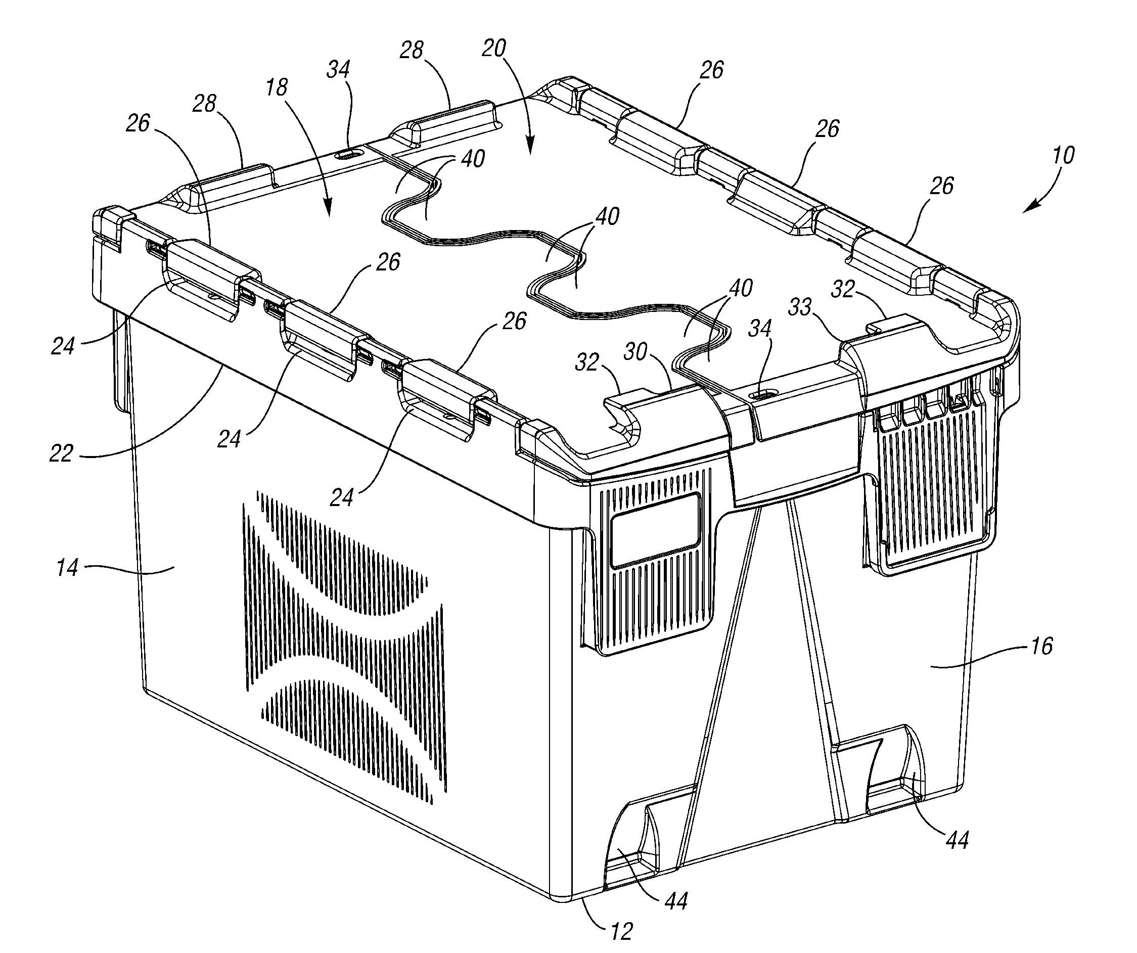
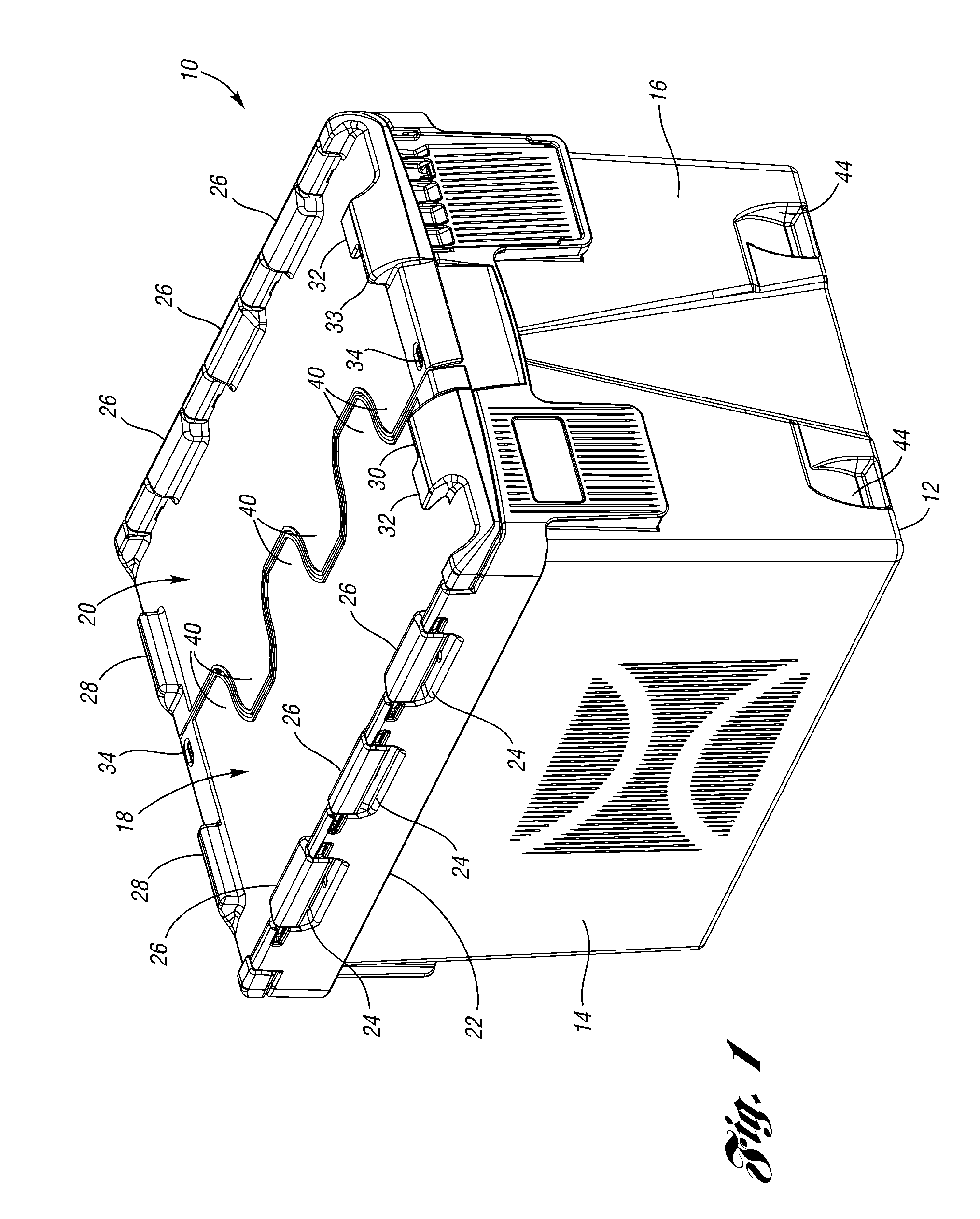
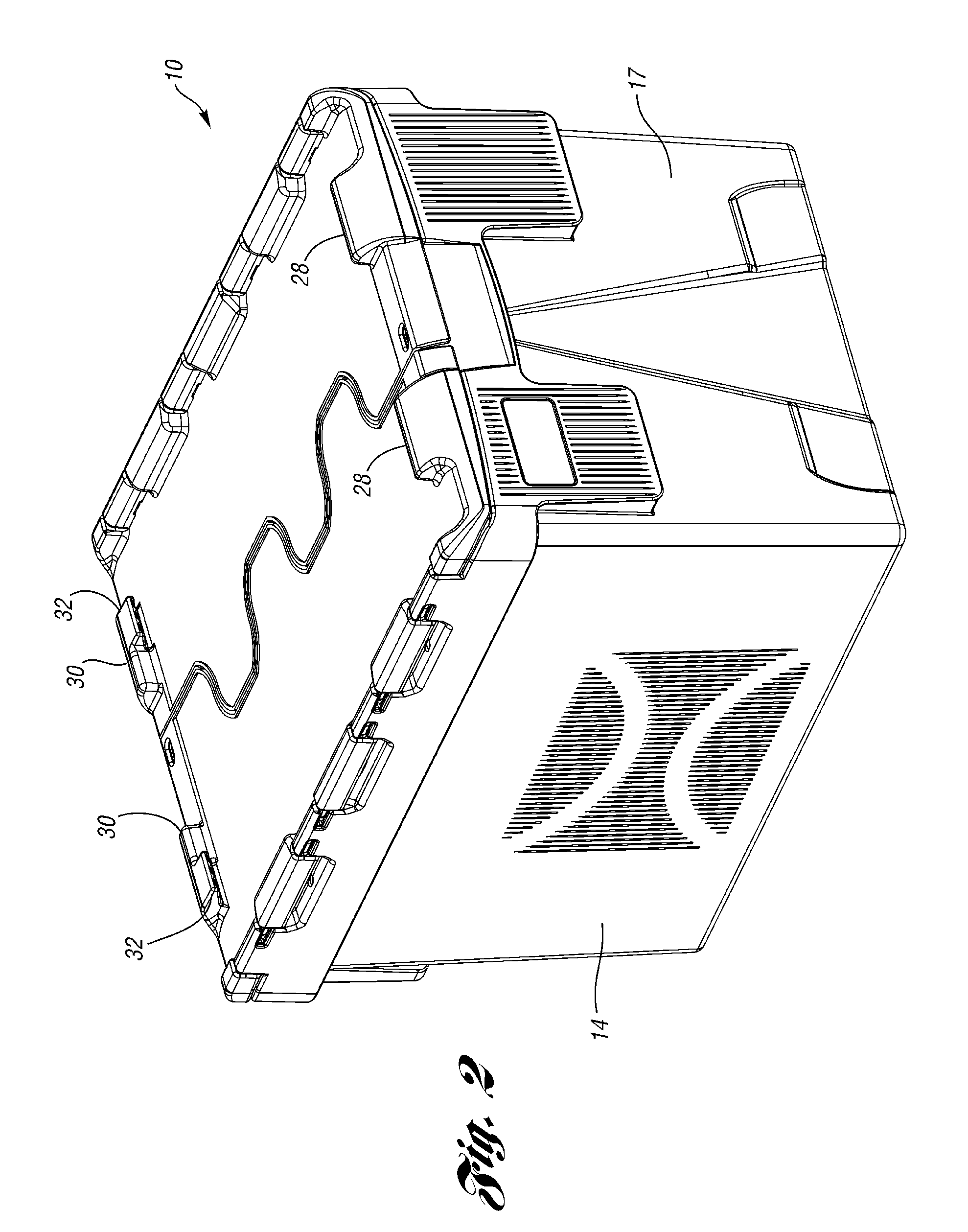
[0039]A storage container 10 according to the present invention is illustrated in FIGS. 1-19. Referring to FIGS. 1 and 2, the storage container 10 includes a base 12 and a pair of opposed side walls 14 and a pair of opposed end walls 16, 17 extending upwardly from the periphery of the base 12. Lid halves 18, 20 are hingeably connected to upper edges of the side walls 14. A flange or lip 22 protrudes outward from the upper edge of the side walls 14 and includes a plurality of hinge receivers 24 formed therein. The hinge receivers 24 each hingeably retain a hinge member 26 formed integrally with one of the lid halves 18, 20.

[0040]Each of the lid halves 18, 20 further includes stops 28, 30 projecting upwardly from opposite edges above the end walls 16, 17. The stops 30 above end wall 16 also include lateral projections 32 extending from the stops 30. The end wall 16 includes a pair of recesses 44 adjacent the base 12. The recesses 44 are aligned with the lateral projections 32 on the s...

second embodiment

[0051]FIGS. 20-27 illustrate a storage container 110 according to the present invention. To the extent not stated or illustrated otherwise, the storage container 110 is similar to the container 10 of FIGS. 1-19, the description of which is hereby incorporated by reference. Components corresponding to those of FIGS. 1-19 are indicated with the same reference numerals prefixed with a “1.” The description of the storage container 110 will therefore focus on three additional features, which could also be incorporated into the storage container 10 of FIGS. 1-19.

[0052]First, referring to FIGS. 20 and 27, the lid half 118 includes a pocket 185 for holding an identification ticket T (ticket T is shown only in FIG. 27) for shipping the storage container 110. The pocket 185 includes a lower surface 186 and a peripheral tab 187 spaced away from the lower surface. The peripheral tab 187 retains the ticket in the pocket 185 and extends about most of the periphery of the pocket 185 except for an ...


PUM


Abstract

A storage container includes a base having side walls and end walls extending upwardly from the base. Lid halves are hingeably connected to upper edges of the side walls. A security recess is formed in the side walls adjacent to each hinge and corresponds with a security tab projecting from the lid halves preventing vertical movement of the outer edge of the lid half when the lid is in the closed position. The lid halves also include a lip adjacent to the hinge and upper and lower leaves that overlap with the opposing lid half to prevent moisture from seeping into the storage container.

Description

[0001]This application claims priority to U.S. Provisional Application Ser. No. 60 / 655,834 filed Feb. 22, 2005.BACKGROUND OF THE INVENTION[0002]This invention relates to a storage container and more particularly to a storage container with improved tamper-resistant features.[0003]Known portable storage containers include two end walls and two side walls extending upwardly from the periphery of a base. Lid halves are each hingeably connected to an upper edge of one of the side walls. Apertures in the overlapping edges of the lid halves are aligned with one another and with apertures through the upper edges of the end walls. Locks through the apertures secure the container closed. Overlapping, interlocking leaves at inner edges of the lid halves prevent intrusion between the lid halves.[0004]In some known containers, it is possible to disassemble the hinged connection of the lid halves to the side walls. Therefore, even though the inner edges of the lid halves are secured, the contain...

Claims


Application Information

Patent Timeline
Patent Type & Authority Patents(United States)
IPC IPC(8): B65D45/16B65D51/04
CPCB65D1/22B65D21/064B65D43/164E05D7/1066B65D43/165B65D2251/1083E05Y2900/602E05Y2999/00B65D43/22
Inventor BALTZ, KYLE L.REHRIG, WILLIAM J.
Owner REHRIG PACIFIC CO INC
Learn More