
Combined footwear and associated fastening accessory

a technology of footwear and accessories, applied in the direction of snap fasteners, buckles, uppers, etc., can solve the problems of lace weakening, lace slipping, time-wasting to tie and untie shoelaces,

Inactive Publication Date: 2011-11-22
RIVAS ROGUE
View PDF13 Cites 103 Cited by
  • Summary
  • Abstract
  • Description
  • Claims
  • Application Information

AI Technical Summary

Benefits of technology

[0016]Also, a mechanism may be included for selectively adjusting the tension in each of the arms by rotating the housing along clockwise and counter clockwise directions while maintaining the fasteners directly connected to the apertures. The mechanism provides the unpredictable and unexpected benefit of allowing the user to tighten the footwear around their foot by simply rotating the housing, a feature not rendered obvious by one skilled in the art.
[0019]The top end of the spring member may be dynamically abutted against the top cap while the bottom end of the spring member may be statically coupled to the bottom surface of the base member. In this manner, the top cap may freely rotate along the top end of the spring member during the tension adjusting procedures. In addition, the base member preferably remains statically situated on the tongue during the tension adjusting procedures. This is advantageous because it may prevent the base member from being pulled in any one direction when the user rotates the cap to add tension to the arms and thereby tighten the footwear to the desired fit.
[0024]In addition, the arms may be maintained at rotatably displaced positions and may thereby be locked at a tensioned position when the top cap is released to the raised position and the fingers re-engage the notches respectively. The tension of the arms may be increased when the proximal ends of the arms are shifted to the rotatably displaced positions and maintained within the housing respectively. Thus, by depressing the top cap and moving it along either direction, the user may advantageously adjust the tension of the arms and corresponding tightness of the shoe in relation to the user's foot, and thereby release the top to relock the fingers into the notches.

Problems solved by technology

However, it is time-wasting to tie and untie the shoelace when wearing and removing the shoe.
Problems inherent in lace closure systems includes unwanted tightening of knots caused by tension in laces occurring through everyday use of shoe, and weakening and eventual breakage of lace at points where the lace rubs against eyelets of the shoe.
Lace closure systems are also impractical and undesirable for use by persons with rheumatoid arthritis, or persons with weight problems, or injuries which make it difficult for them to bend over for the period of time required to perform lace closure.
Unfortunately, this prior art reference does not disclose a centrally located lighted disc to provide a fashionable accessory.
Unfortunately, this prior art reference does not disclose a non-laced method of keeping the shoe panels intact.
Unfortunately, this prior art reference also does not disclose a non-laced method for keeping the shoe panels intact, nor does it feature a centrally located lighted disc.

Method used


Image

  • Combined footwear and associated fastening accessory
  • Combined footwear and associated fastening accessory
  • Combined footwear and associated fastening accessory

Examples


Embodiment Construction

[0041]The present invention will now be described more fully hereinafter with reference to the accompanying drawings, in which a preferred embodiment of the invention is shown. This invention may, however, be embodied in many different forms and should not be construed as limited to the embodiment set forth herein. Rather, this embodiment is provided so that this application will be thorough and complete, and will fully convey the true scope of the invention to those skilled in the art. Like numbers refer to like elements throughout the figures.

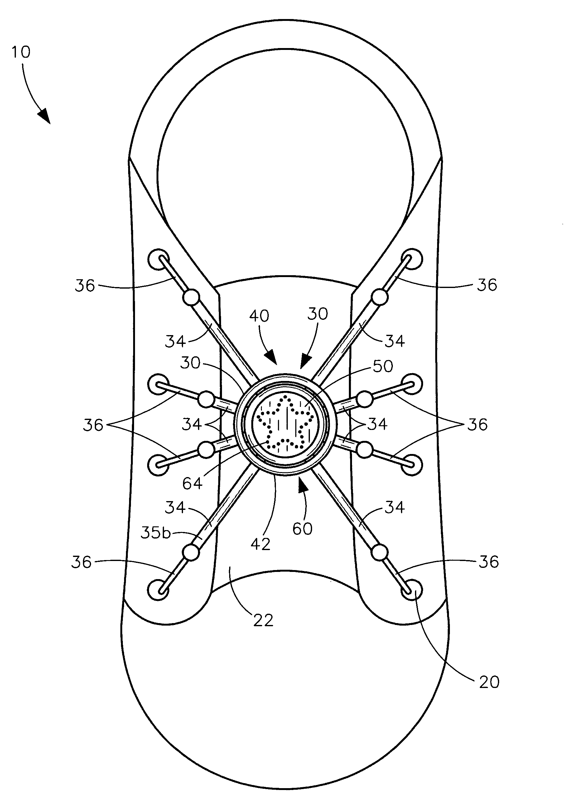
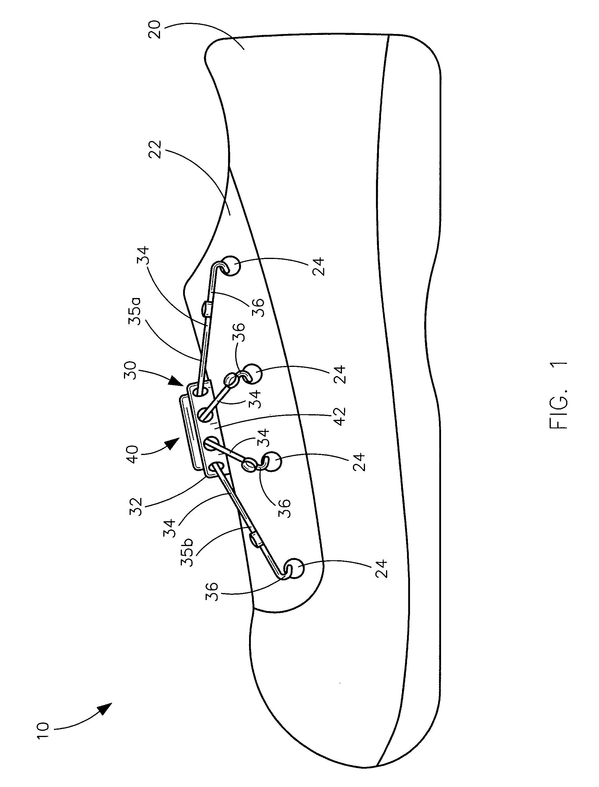
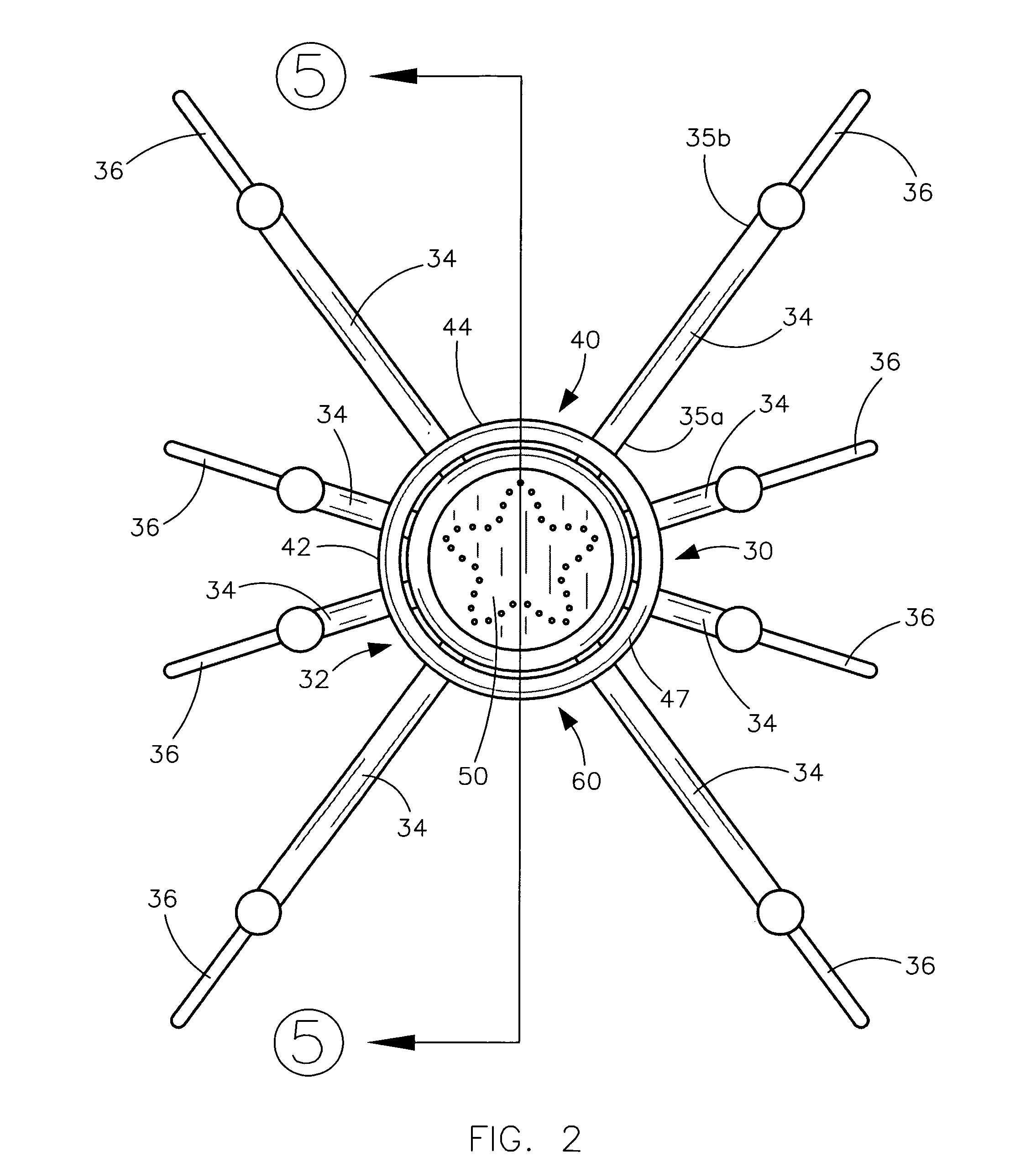
[0042]The assembly of this invention is referred to generally in FIGS. 1-7 by the reference numeral 10 and is intended to provide a combined footwear and associated fastening accessory. It should be understood that the combined footwear and associated fastening accessory 10 may be used to fasten many different types and styles of footwear, including tennis shoes or boots, and should not be limited in use to the applications addressed herein.

[...


PUM


Abstract

A combined footwear and associated fastening accessory for use therewith may include footwear with a tongue, a plurality of apertures, and a fastening accessory removably coupled to the footwear. The accessory may include a housing removably seated directly on the tongue. A plurality of deformably resilient elastic arms may be coupled to the housing and radially extended from the housing. The arms may include fasteners terminating at corresponding apertures and removably connected thereto, such that the housing may remain centrally aligned on the tongue and prohibited from becoming disengaged. Also, a mechanism may be included for selectively adjusting tension in each of the arms by rotating the housing along clockwise and counter-clockwise directions, while maintaining the fasteners directly connected to the apertures. Further, a mechanism for illuminating the housing when the top cap is in a raised position may be included and may illuminate the housing during walking conditions.

Description

CROSS REFERENCE TO RELATED APPLICATIONS[0001]Not Applicable.STATEMENT REGARDING FEDERALLY SPONSORED RESEARCH OR DEVELOPMENT[0002]Not Applicable.REFERENCE TO A MICROFICHE APPENDIX[0003]Not Applicable.BACKGROUND OF THE INVENTION[0004]1. Technical Field[0005]This invention relates to illuminable footwear shoelace accessories and, more particularly, to a combined footwear and associated fastening accessory for use therewith.[0006]2. Prior Art[0007]A shoe usually includes a pair of eyelet tabs and a shoelace. Each of the eyelet tabs is formed with a plurality of eyelets. The shoelace is typically strung through the eyelets to form a criss-cross pattern on the eyelet tabs, and is then tied into a knot so as to tighten the shoe. However, it is time-wasting to tie and untie the shoelace when wearing and removing the shoe. Many shoe lacing systems have been designed to provide a faster and more convenient way of securing a shoe onto the foot.[0008]The vast majority of these systems are “lace...

Claims


Application Information

Patent Timeline
IPC IPC(8): A43C11/20
CPCA43B3/001A43C11/165A43C11/002Y10T24/2183A43B3/36
Inventor RIVAS, ROGUE
Owner RIVAS ROGUE
Learn More