
Electronic cigarette

Active Publication Date: 2018-10-11
MICROJET TECH
View PDF10 Cites 2 Cited by
  • Summary
  • Abstract
  • Description
  • Claims
  • Application Information

AI Technical Summary

Benefits of technology

The present invention provides an electronic cigarette that can control the amount of liquid transferred to the atomizer, resulting in a better taste and less liquid leakage. Additionally, the electronic cigarette allows for quick inhalation of a great amount of atomized vapor by detecting air pressure and adjusting the speed of atomizing and providing the liquid accordingly. This results in a consistent user experience.

Problems solved by technology

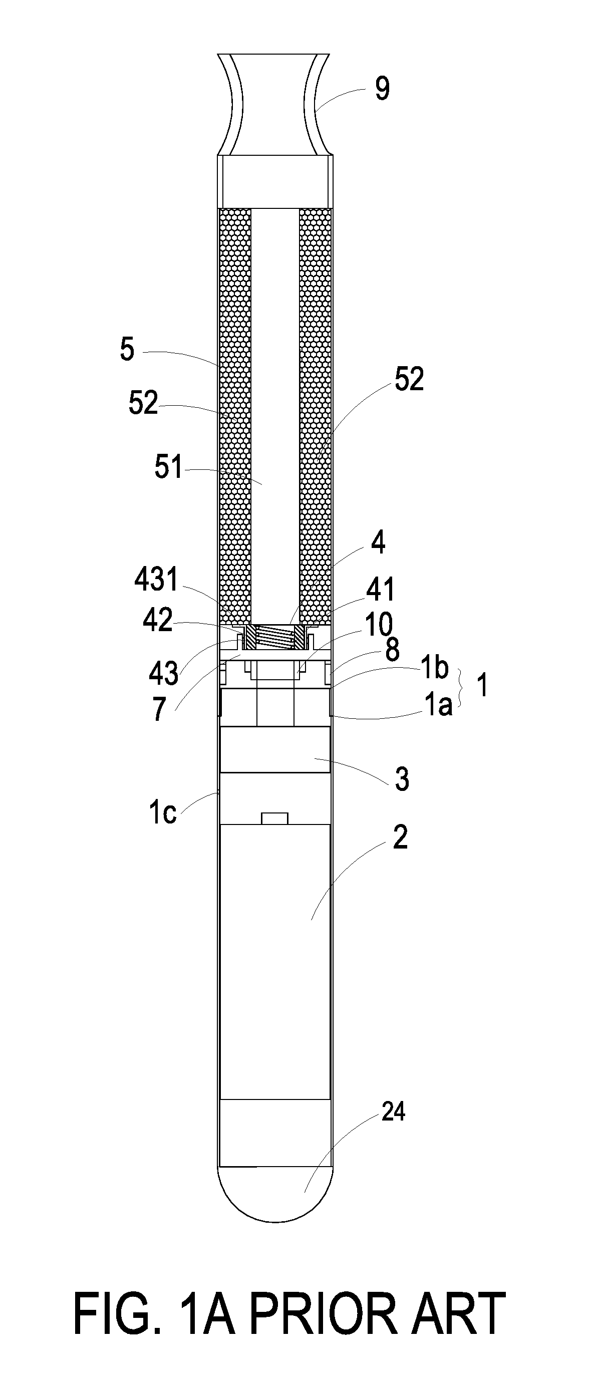
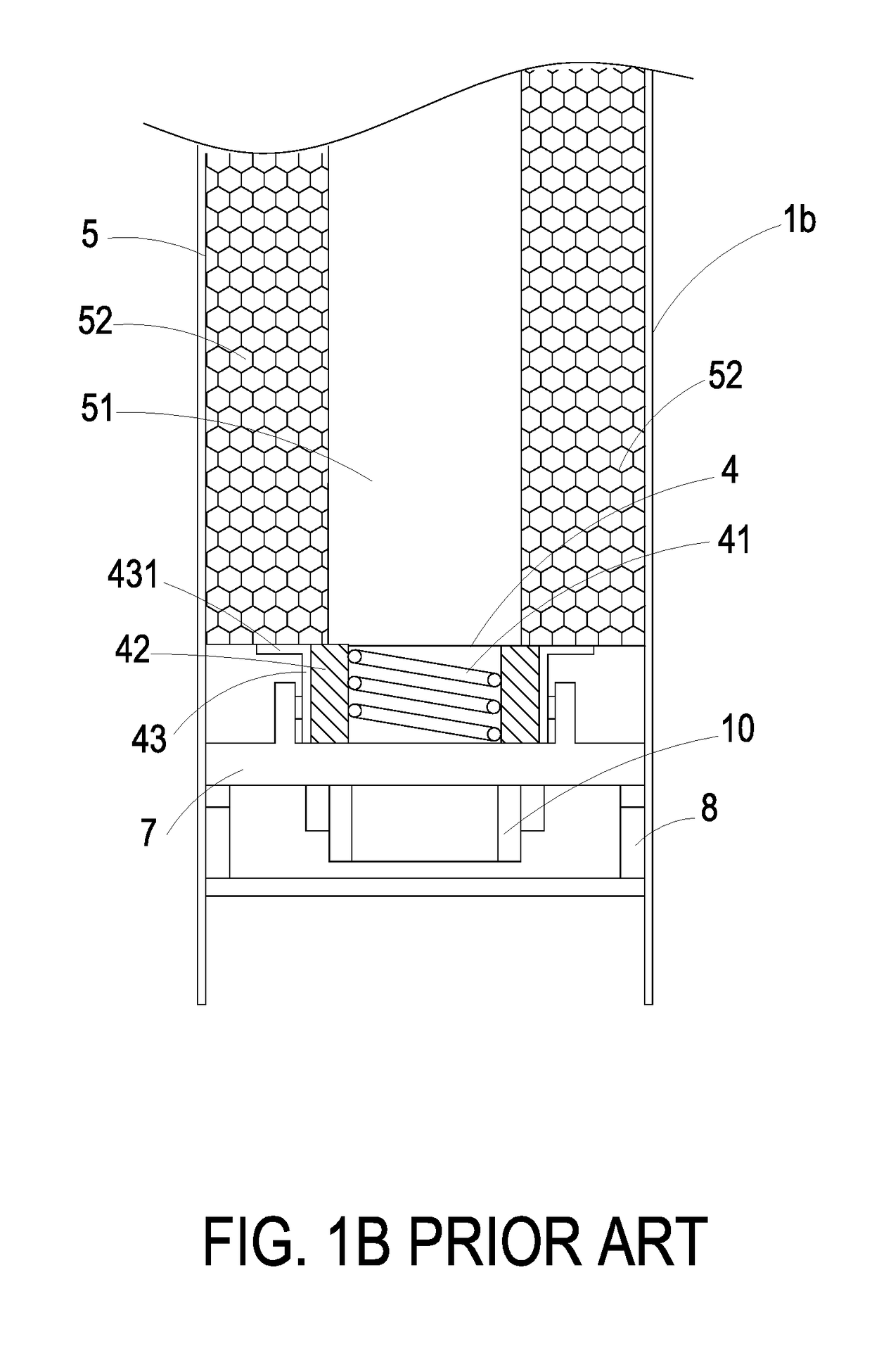
Firstly, it is difficult to precisely control the amount of the cigarette liquid to be transferred to the liquid infiltration part 42 through the communication part 431 of the liquid transfer part 43. Consequently, the cigarette liquid is not uniformly absorbed by the liquid infiltration part 42. In case that a site of the liquid infiltration part 42 absorbs a small amount of the cigarette liquid, the liquid drop is not uniformly generated. After the liquid drop of the cigarette liquid is heated by the electric heater 41, the atomized vapor has a burning taste that is unpleasing to the user.
Secondly, since the amount of the cigarette liquid to be transferred to the liquid infiltration part 42 cannot be precisely controlled, another problem occurs. Especially when the mouthpiece 9 faces up, the force of gravity continuously transfers the cigarette liquid from the liquid container 52 to the liquid infiltration part 42. Once the cigarette liquid absorbed by the liquid infiltration part 42 reaches a saturation state, the cigarette liquid drops down to the bracket 7 and the intake-and-electric-connection element 10. Then, the cigarette liquid drops down through the sensing unit 3 and leaks out from the at least one inlet 1c. Meanwhile, a liquid leakage problem occurs.
Moreover, there are some differences between the electronic cigarettes and the real cigarettes.
However, while the user smokes the conventional electronic cigarette, the electric power to be transmitted to the electric heater and the heating speed cannot be adjusted.
Since the cigarette liquid of the conventional electronic cigarette is provided according to a siphon effect, the speed of providing the cigarette liquid is too slow.
Under this circumstance, the amount of the atomized vapor is insufficient or the atomized is burnt out.
That is, the conventional method of atomizing the cigarette liquid of the electronic cigarette still has some drawbacks.
The above problems lead to significant differences between the real cigarette and the electronic cigarette.

Method used


Image

  • Electronic cigarette
  • Electronic cigarette
  • Electronic cigarette

Examples


Embodiment Construction

[0034]The present invention will now be described more specifically with reference to the following embodiments. It is to be noted that the following descriptions of preferred embodiments of this invention are presented herein for purpose of illustration and description only. It is not intended to be exhaustive or to be limited to the precise form disclosed.

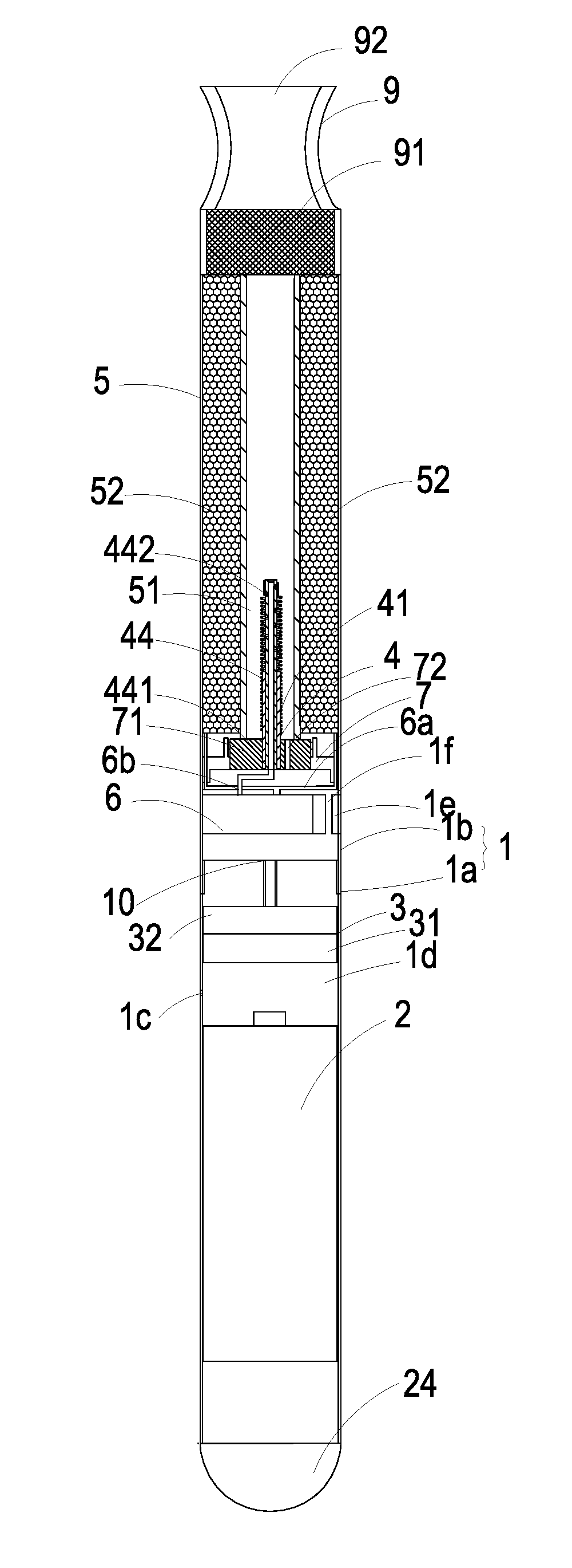
[0035]FIG. 2A is a schematic cross-sectional view illustrating an electronic cigarette according to an embodiment of the present invention. FIG. 2B is a schematic cross-sectional view illustrating some components near the power supply device of the electronic cigarette according to the embodiment of the present invention. FIG. 2C is a schematic cross-sectional view illustrating some components near the atomizer of the electronic cigarette according to the embodiment of the present invention. As shown in FIGS. 2A, 2B and 2C, the electronic cigarette of the present invention comprises a casing 1, a power supply device 2, a sensing ...


PUM


Abstract

An electronic cigarette includes a power supply device, a sensing unit, an atomizer, a liquid storage structure and a fluid transportation device. The atomizer includes an electric heater and a liquid conduit. The liquid conduit has an input port at one end and plural perforations at the other end, and the electric heater is disposed around the liquid conduit. The liquid storage structure includes a passageway and a liquid container. A cigarette liquid is stored in the liquid container. The fluid transportation device includes an input channel and an output channel. The input channel is in communication with the liquid container. The output channel is in communication with the liquid conduit of the atomizer. The cigarette liquid is transferred to the atomizer at a certain amount. Consequently, an atomized vapor is generated.

Description

FIELD OF THE INVENTION[0001]The present invention relates to an electronic cigarette, and more particularly to an electronic cigarette with a fluid transportation device.BACKGROUND OF THE INVENTION[0002]Nowadays, electronic cigarettes are widely used to replace the conventional tobacco cigarettes. FIG. 1A is a schematic cross-sectional view illustrating a conventional electronic cigarette. FIG. 1B is a schematic cross-sectional view illustrating the structure of the atomizer of the conventional electronic cigarette. As shown in FIGS. 1A and 1B, the electronic cigarette comprises a first casing 1a, a second casing 1b, a power supply device 2, a sensing unit 3, an atomizer 4 and a liquid storage structure 5. The first casing 1a and the second casing 1b are thin-wall metal pipes, e.g., stainless steel pipes. The power supply device 2, the sensing unit 3, the atomizer 4 and the liquid storage structure 5 are disposed within the first casing 1a and the second casing 1b. After the first c...

Claims


Application Information

Patent Timeline
IPC IPC(8): A24F47/00A24F7/04H05B3/44F16K7/00G05B15/02A24F40/10A24F40/485
CPCA24F47/008A24F7/04H05B3/44F16K7/00G05B15/02A24F40/485A24F40/10A24F40/48F04B43/046
Inventor CHEN, SHIH-CHANGMO, LI-PANGCHEN, SHOU-HUNGCHEN, MEI-YENHUANG, CHI-FENGHAN, YUNG-LUNG
Owner MICROJET TECH
Learn More