
DLL-based multiphase clock generator

a multi-phase clock and generator technology, applied in the direction of pulse manipulation, pulse automatic control, pulse technique, etc., can solve the problems of deterioration of the performance of the whole circuit, inability to correctly generate output frequencies, etc., to reduce the load burden of voltage controlled delay lines, widen the operation band of frequency multipliers, and calibrate delay mismatches

Active Publication Date: 2011-11-15
KOREA UNIV IND & ACADEMIC CALLABORATION FOUND
View PDF3 Cites 11 Cited by
  • Summary
  • Abstract
  • Description
  • Claims
  • Application Information

AI Technical Summary

Benefits of technology

The solution reduces the load burden on the voltage controlled delay line, widens the operation band of the frequency multiplier, calibrates delay mismatches, and effectively suppresses power source voltage noises, ensuring stable and accurate high-frequency multiphase clock generation.

Problems solved by technology

However, these conventional delay-locked loop-based multiphase clock generators have a problem of harmonic lock that two inputs of a phase detector are locked to more than two periods and further a problem that output frequencies may not be correctly generated due to a layout mismatch and a delay mismatch of delay cells constituting a voltage controlled delay line, which is caused by change of process / power source voltage / temperature.
In addition, power source voltage noises are generated by parasitic inductance components existing in metal conductive lines which are in proportion to variation of current flowing through the lines.
Therefore, if current flowing through a conductive line is suddenly changed due to a sudden change of an operation frequency, power source voltage noises are increased, which may result in deterioration of performance of the whole circuit.

Method used


Image

  • DLL-based multiphase clock generator
  • DLL-based multiphase clock generator
  • DLL-based multiphase clock generator

Examples


Embodiment Construction

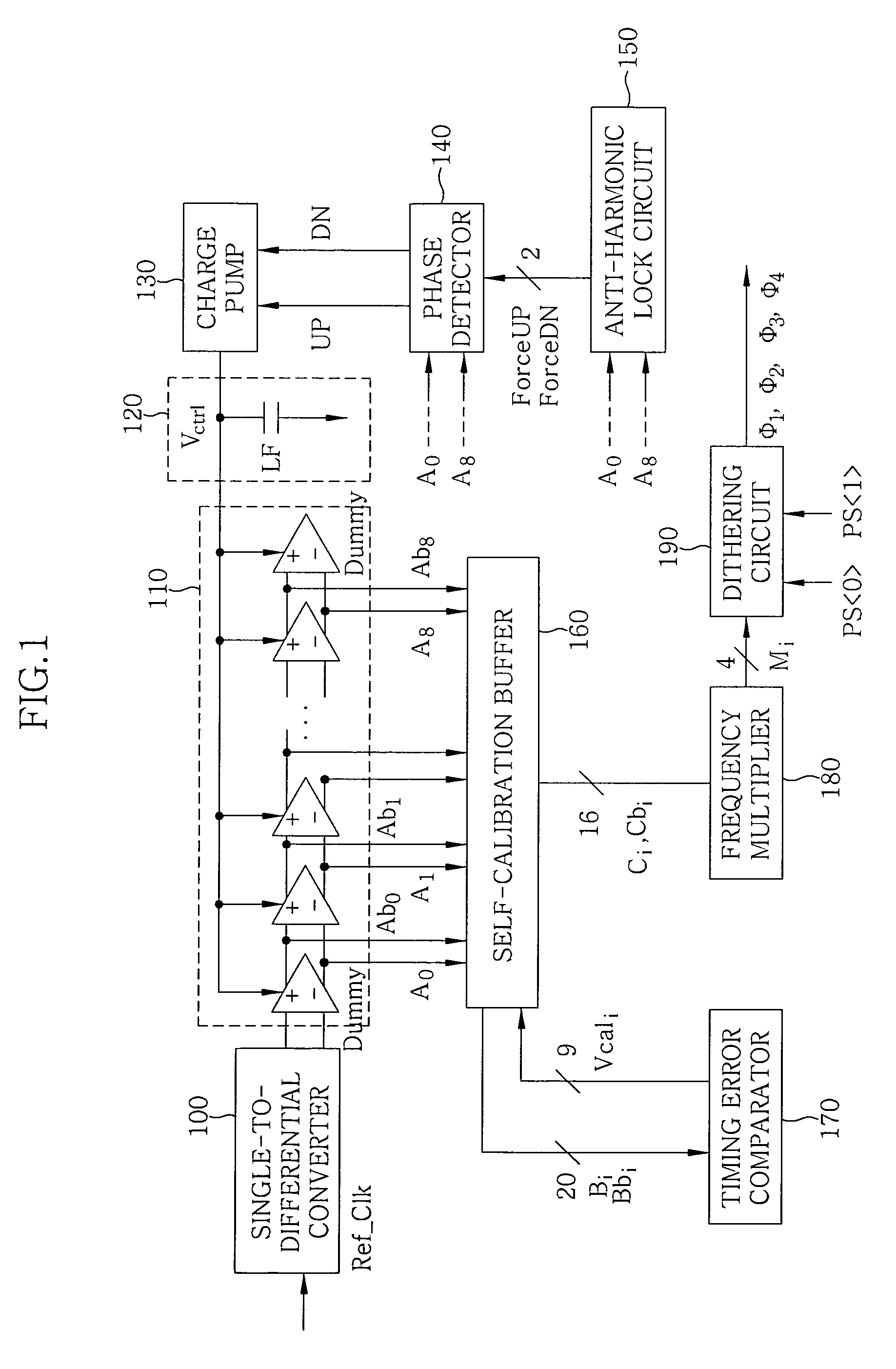
[0052]The present invention addresses a frequency multiplication technique and suggests a multiphase clock generator which is capable of preventing a harmonic lock in advance even when an input clock with a wider band width is input by deleting unnecessary pulses existing on a certain period of the input clock using an anti-harmonic lock block, and then including the pulses existing on the input clock in a certain period of a reference clock. In addition, the present invention suggests a delay-locked loop-based multiphase clock generator which is capable of removing interior noises caused by sudden change of a multiplication clock using a dithering circuit.

[0053]Although high frequency operation of detailed circuits constituting a delayed-lock loop has to be guaranteed in order to generate a high output frequency in the prior art, the present invention can alleviate design burden and reduce power consumption by generating a multiphase clock whose frequency is double as high as a ref...


PUM


Abstract

The present invention relates to a delay-locked loop-based multiphase clock generator that generates a plurality of multiphase clocks from an input clock signal using a voltage controlled delay line including a plurality of dummy cells. The delay-locked loop-based multiphase clock generator includes an anti-harmonic lock circuit that receives an input clock and a reference clock of multiple clocks, determines whether a pulse signal derived from the input clock is within a normal locking range of the reference clock, and outputs a compulsory control signal to compulsorily control an output signal of a phase detector if it is determined that the pulse signal is not within the normal locking range.

Description

CROSS-REFERENCE TO RELATED APPLICATION[0001]This application claims the benefit of Korean Application No. 10-2008-0069755, filed on Jul. 17, 2008, and Korean Application No. 10-2008-0074503 filed on Jul. 30, 2008, with the Korean Intellectual Property Office, the disclosure of which are incorporated herein by reference.BACKGROUND OF THE INVENTION[0002]1. Field of the Invention[0003]The present invention relates to a multiphase clock generator, and more particularly, to a delay-locked loop-based multiphase clock generator.[0004]2. Description of the Related Art[0005]With increase of data processing speed of computers and digital communication equipments, multiphase clocks have been increasingly used for increasing operation band width. A multiphase clock can overcome a limitation on clock speed of a microprocessor and may be used to process data with a bit rate higher than an internal operation frequency in a communication system. Such a multiphase clock is being widely used for high...

Claims


Application Information

Patent Timeline
Patent Type & Authority Patents(United States)
IPC IPC(8): H03L7/06
CPCH03K5/1565H03K5/133H03L7/0812H03K2005/00026
Inventor KIM, CHULWOOKOO, JA BUMOK, SUNG HWA
Owner KOREA UNIV IND & ACADEMIC CALLABORATION FOUND
Learn More