
Surgical sensor

a sensor and surgical technology, applied in the field of surgical sensors, can solve the problems of difficult to track the relative movement of multiple anatomical structures, largely limited external tracking of anatomical structures, and inability to accurately identify patients,

Active Publication Date: 2011-11-15
MEDTRONIC NAVIGATION INC
View PDF658 Cites 177 Cited by
  • Summary
  • Abstract
  • Description
  • Claims
  • Application Information

AI Technical Summary

Benefits of technology

The patent describes a system for detecting movement of anatomical structures during medical procedures without the need for external equipment. The system includes an anatomical anchor / sensor and a receiver that senses signals generated external to the anchor. The system can be used with minimal invasive procedures and can serve as both a preprocedural and intraprocedural fiducial marker. The system allows for movement detection with five or six degrees of freedom and can track the relative movement of instruments and anatomical structures. The technical effects of the patent include improved accuracy and efficiency in medical procedures and reduced risk of complications.

Problems solved by technology

Until now, the tracking of anatomical structures has been largely limited to external tracking, either by taping a sensor to a patient's skin, or by affixing an external clamp to the patient, such as a Mayfield clamp, attached externally to a patient's head.
While such related art systems may generally be reliable, their structure is somewhat cumbersome, especially when the movement of multiple anatomical structures needs to be tracked.
In addition, the use of the tracking elements and receiving array requires an unobstructed line of sight therebetween which not only limits implantation within a patient, but also can lead to interference.
For these reasons, in procedures such as those involving the spine or the reconstruction or repair of vertebral bodies, fractured skulls, fragmented bones, or other damaged boney structures, it has been somewhat difficult to track the relative movement of multiple anatomical structures.

Method used


Image

  • Surgical sensor
  • Surgical sensor
  • Surgical sensor

Examples


Embodiment Construction

The following description of various embodiments is merely exemplary in nature and is in no way intended to limit the present teachings, its application, or uses.

The teachings will now be described in connection with the Figures wherein like parts are numbered with the same reference numerals for ease of discussion.

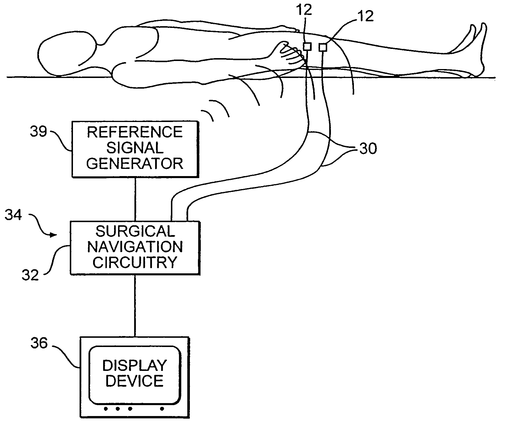
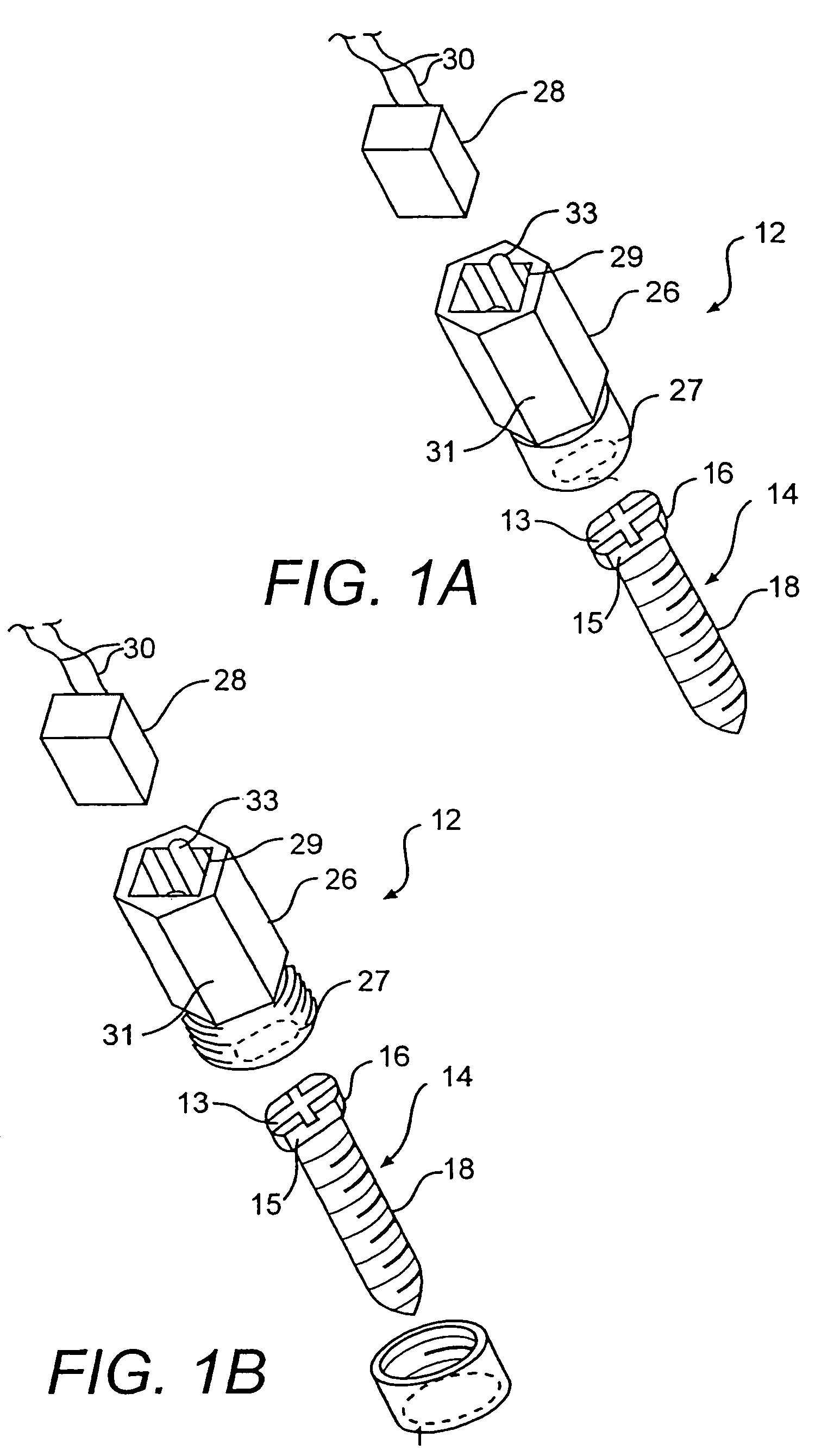
In accordance with the teachings, there is provided an integrated surgical anchor / localization sensor. An example of such an integrated unit is designated by reference number 12 in FIG. 1.

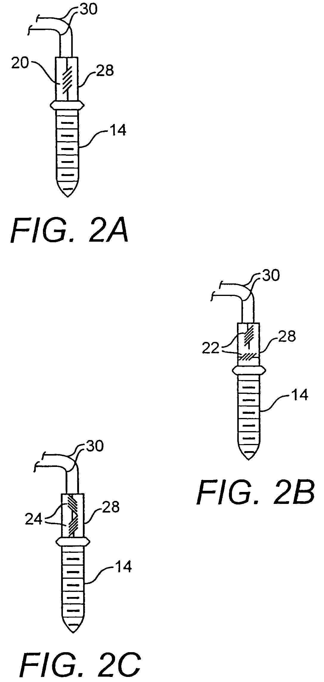
According to the invention, the anchor is configured to be secured to an anatomical structure. As illustrated in FIG. 1, an anchor in accordance with the invention may, by way of example, include a surgical screw 14. Screw 14 has a head portion 16, and a threaded portion 18. The threaded portion 18 is configured to be secured into boney structure such as portions of long bones, vertebral bodies, the skull, or any other boney anatomical structure. In an preferred embodiment, the anchor ma...


PUM


Abstract

An integrated surgical anchor / localization sensor is disclosed. The anchor is adapted to be secured to an anatomical structure and contains a sensor housing. A receiver is located within the sensor housing and is adapted to sense reference signals generated by a surgical guidance system. A transmitter, connected to the receiver, conveys to a processor signals received by the receiver, so that the signals transmitted by the receiver are indicative of a current position of the anchor. Various other structures and methods are also disclosed.

Description

FIELDThe present teachings relate to a surgical sensor which may be integrated with an anatomical anchor. The sensor has particular applicability in surgical procedures where it is desirable to track the relative movement of one or more structures.BACKGROUNDMany surgical procedures are planned and guided using images obtained from imaging systems such as magnetic resonance imagers (MRIs), computer tomographic imagers (CTs), x-ray imagers, positron emission tomographic (PET) scanners, and photo-emission computer technology (SPECT). These systems permit physicians to obtain detailed preoperative (or intraoperative) views of anatomical structures using noninvasive procedures. Once these images are obtained, the physician typically uses the images to plan a corrective surgical procedure. With the patient lying on an operating table, the images may be “registered” with the corresponding physical space of the patient, and displayed on a screen in the operating room (OR). As the physician ...

Claims


Application Information

Patent Timeline
Patent Type & Authority Patents(United States)
IPC IPC(8): A61B5/103A61B19/00
CPCA61B19/5244A61B19/54A61B2017/00477A61B2019/5251A61B2019/5272A61B2019/5416A61B2019/547A61B2019/5483A61B2019/5487A61B2090/3983A61B2034/2072A61B2090/3916A61B34/20A61B2034/2051A61B90/39A61B2090/397A61B2090/3987
Inventor MARTINELLI, MICHAEL AHUNTER, MARK WMCCOID, SHERIKESSMAN, PAUL
Owner MEDTRONIC NAVIGATION INC
Learn More