Liquid cleaning device

a cleaning device and liquid technology, applied in distillation regulation/control, steam generation using steam absorption, combustion air/fuel air treatment, etc., can solve the problem of difficult to know when the filter is full, difficult to clean the filter, and easy to lose the effect of activated carbon quickly

Inactive Publication Date: 2011-11-08
PURITY AB
View PDF7 Cites 4 Cited by
  • Summary
  • Abstract
  • Description
  • Claims
  • Application Information

AI Technical Summary

Benefits of technology

[0018]In accordance with the invention, the advantage is obtained that the liquid cleaning device, after the boiling point of the liquid having been reached, can proceed to transport liquid at controlled power, during fixed time, which gives a final product that contains very small amounts of volatile substances. By the automatic reduction of the power level of the heating member, the advantage is further obtained that a user does not need to look after the cleaning process in order to know when the power should be reduced, as well as the advantage that the user knows when a satisfactory cleaning result has been attained.
[0019]According to an advantageous embodiment of the invention, the change-over member is formed so that the automatic reduction of the power level of the heating member is triggered by the boiling of the liquid. In this way, the transport of liquid continues directly at the reduced power after the boiling point of the liquid having been reached, which entails a quick cleaning process and thereby also a smaller energy consumption for the proper cleaning process, which in turn is positive from an economic aspect. Furthermore, the advantage is obtained that a smaller quantity of liquid is lost than in long and uncontrolled boiling processes. According to an alternative embodiment, the automatic reduction of the power level of the heating member may of course also be triggered by a timer. This preferably takes place so that the timer is set so that the power level is reduced after a certain time counted from when the liquid cleaning device is started. The setting of the timer may advantageously be adjustable by means of, for instance, a knob.
[0020]According to an additional advantageous embodiment, the liquid cleaning device may comprise a timer that is formed so that it adjusts the length of the processing time after the boiling of the liquid has started. The setting of the timer may, for instance, be carried out by means of a knob arranged on the timer, which enables a quick and simple setting of the length of the processing time. This entails that it is possible to decide in a simple way in advance and directly upon the beginning of the boiling for how long the cleaning process is wanted to run. Thereby, the cleaning process requires no supervision and a user may spend his / her time with other things while waiting for the cleaning process becoming ready.
[0021]According to another advantageous embodiment, the change-over member may comprise a bimetal that reduces the power level of the heating member. In this way, the process can be controlled and optimized so that the transport of liquid is as good as possible without flashing arising. The bimetal may of course be set to react at different desirable temperatures.

Problems solved by technology

However, traditional filters that are in the form of fine-meshed nets do not stop volatile substances such as chlorine and chlorinated hydrocarbons.
The disadvantage of activated carbon is that it is difficult to know when the filter is full, and in many examinations it has been found that the activated carbon quickly may lose effect upon an unexpected load increase and in that connection further turn into a refuge, nutrition place and breeding ground for bacteria and pyrogenes.
Such an equipment becomes relatively expensive and works satisfactory only if the exchange of roughing filter, ultraviolet lamps, ion exchange mass and activated carbon is handled accurately.
None of these methods, advanced per se, is however entirely efficient in removing chlorine and chlorinated hydrocarbons but have to be supplemented with an activated-carbon final filter.
Even if the load on this final filter is much smaller than on carbon filters in the previously mentioned multi-stage filters, also these have to be exchanged at regular intervals, and the problem with overload remains.
The disadvantages of this simple method in comparison with what has been mentioned previously are foremost three.
The third disadvantage is that the user does not know when a satisfactory result has been attained.
A disadvantage of the liquid cleaning device in the Swedish patent 518 388 is that when the volume of liquid in the product reaches the boiling temperature, the liquid begins to flash at unchanged supply of energy to the cleaning process.
This in turn means that the desirable transport of liquid decreases and that a final product that has not been fully cleaned is obtained.

Method used


Image

  • Liquid cleaning device
  • Liquid cleaning device
  • Liquid cleaning device

Examples


Embodiment Construction

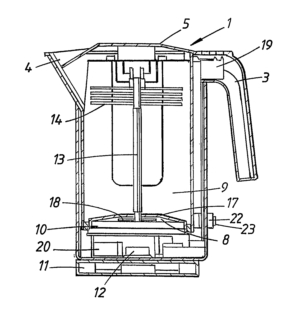
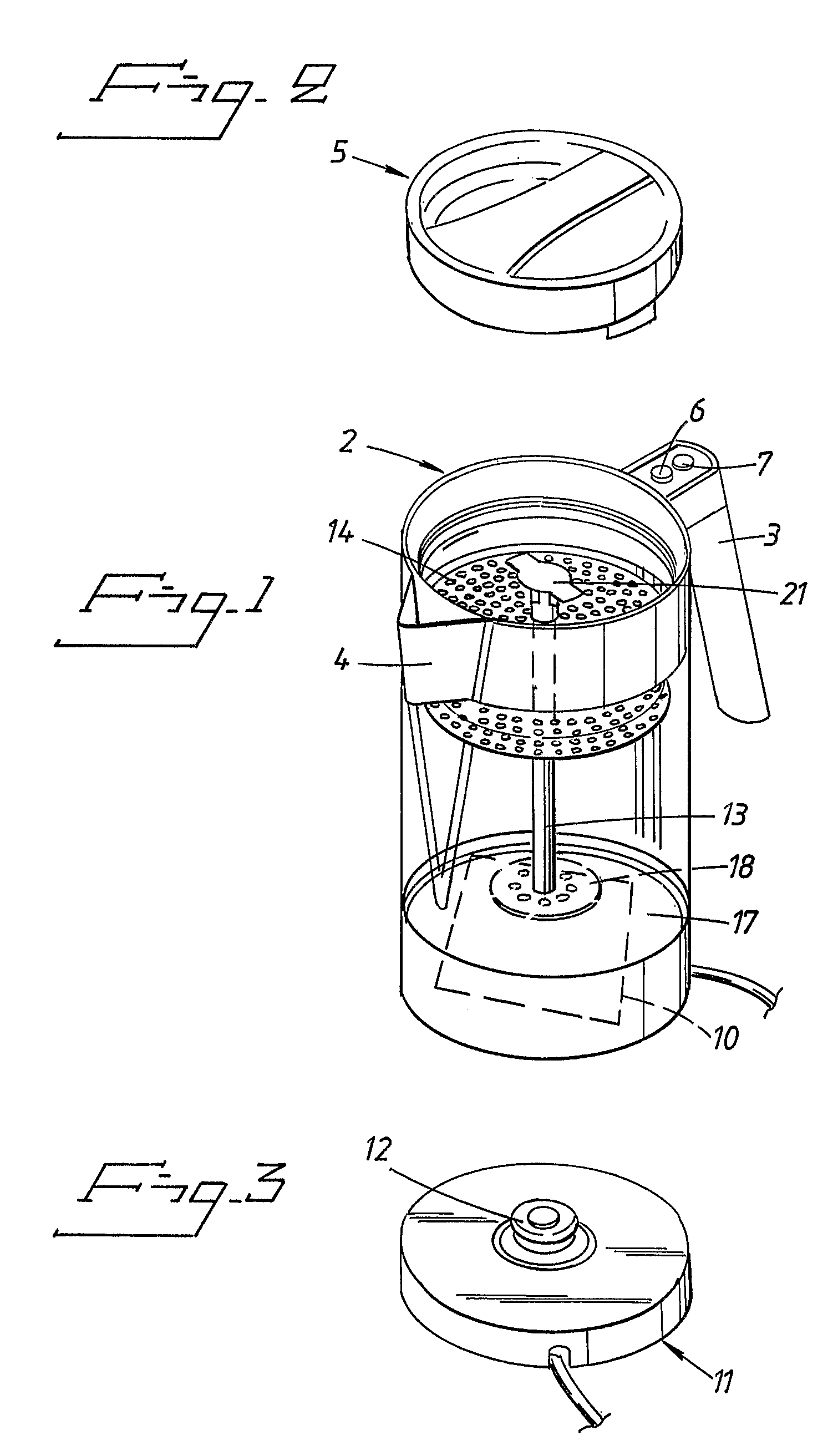
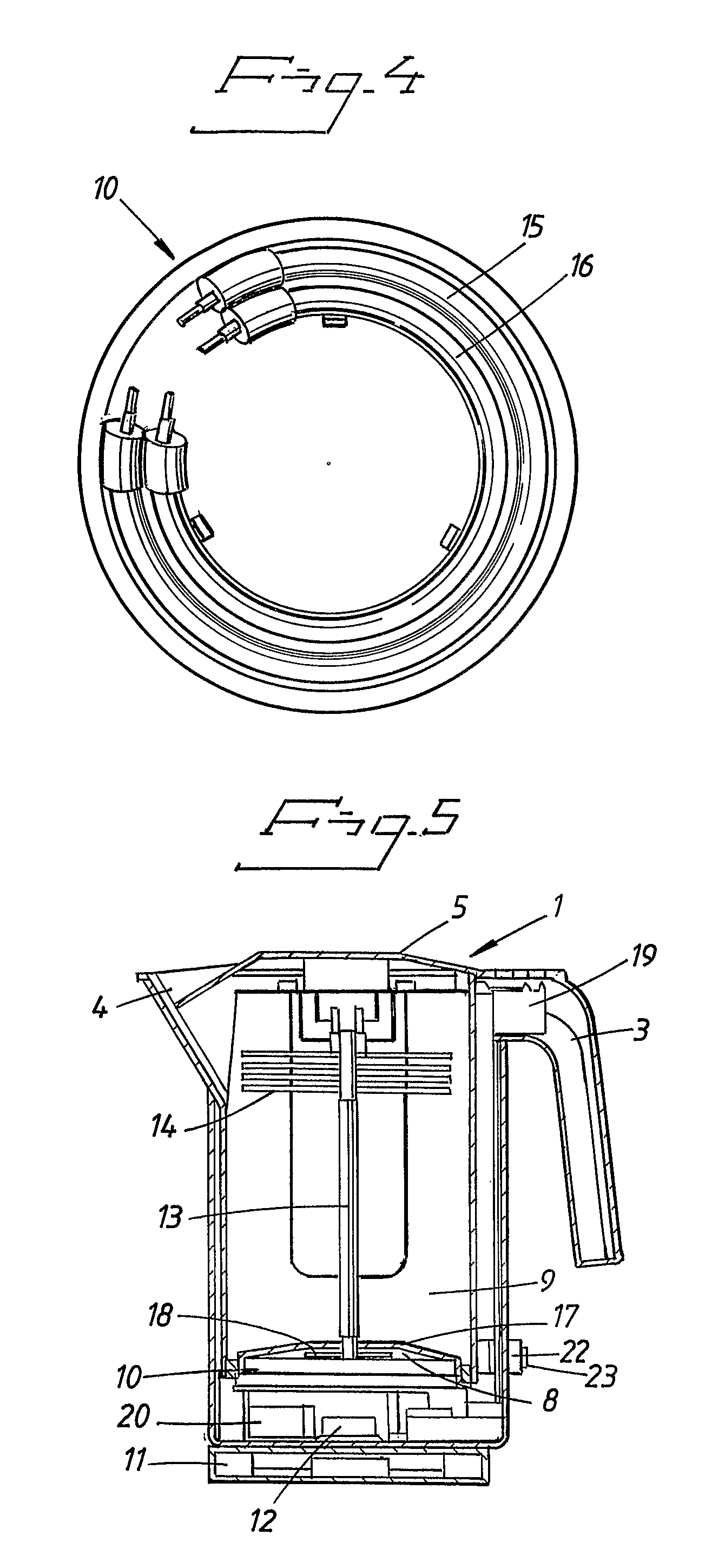
[0029]In FIGS. 1-5, an embodiment of the present invention is shown, applied to a liquid cleaning device intended for purifying liquid from pollutants. However, it should be directly emphasized that the invention is in no way limited to this type of liquid cleaning device, but may be applied to various liquid cleaning devices.

[0030]FIG. 1 shows a perspective view of the liquid cleaning device 1 according to the present invention. The liquid cleaning device 1 comprises a vessel 2, which in the figures looks like an ordinary cylindrical pot having handle 3, spout 4 and lid 5. In order to be able to start and stop the cleaning process by hand, a start button 6 and a stop button 7 are arranged on the handle 3. The vessel 2 consists of a lower chamber 8 and an upper chamber 9, which are divided from each other by means of a cap 17 of some insulating material, see FIG. 5. In the lower chamber 8, the liquid is heated by a heating member 10, which is supplied with electrical energy from a b...


PUM

PropertyMeasurementUnit
areaaaaaaaaaaa
gravityaaaaaaaaaa
power levelsaaaaaaaaaa

Abstract

The invention relates to a liquid cleaning device that is intended for purifying liquid from pollutants, which liquid cleaning device includes a vessel, having a lower chamber and an upper chamber, which lower chamber is connected to a heating member arranged to heat the liquid in said lower chamber, as well as further including a riser and liquid-distributor member, which riser is arranged to transport heated liquid from said lower chamber up to the upper part of said upper chamber, where the liquid-distributor member is arranged to impart the heated liquid an increased area of exposure to surrounding air, the liquid then, by means of the gravity, running back downward outside the riser and being collected in the lower part of the upper chamber of the vessel, said upper chamber and lower chamber being in at least conditioned communication with each other in order to allow transfer of the liquid from the upper chamber to the lower chamber. According to the invention, the heating member is arranged to be capable of assuming at least two power levels and that a change-over member is arranged to automatically reduce the power level of the heating member.

Description

CROSS REFERENCE TO RELATED APPLICATIONS[0001]This application is a National Stage of International Application No. PCT / SE2005 / 001011 filed Jun. 27, 2005, and which claims benefit of Swedish Patent Application No. 0401750-5 filed Jul. 2, 2004, which is incorporated by reference herein in its entirety.TECHNICAL FIELD OF THE INVENTION[0002]The present invention relates to a liquid cleaning device intended for purifying liquid from pollutants, which liquid cleaning device comprises a vessel, having a lower chamber and an upper chamber, which lower chamber is connected to a heating member arranged to heat the liquid in said lower chamber, as well as further comprising a riser and liquid-distributor member, which riser is arranged to transport heated liquid from said lower chamber up to the upper part of said upper chamber, where the liquid-distributor member is arranged to impart the heated liquid an increased area of exposure to surrounding air, the liquid then, by means of the gravity,...

Claims


Application Information

Patent Timeline
Patent Type & Authority Patents(United States)
IPC IPC(8): B01D1/00B01B1/06C02F1/18B01D3/42C02FC02F1/04
CPCB01D1/0017C02F1/003C02F1/18C02F1/048C02F2307/04C02F2209/44
Inventor HOLMBERG, PETER
Owner PURITY AB
Why Eureka
Try Eureka