
Cardiotomy reservoir with blood inflow and outflow connectors located for optimizing operation

a technology of blood inflow and outflow connector, which is applied in the field of cardiacotomy reservoirs, can solve the problems of affecting the operation efficiency of the operation, and the operation is limited, and achieves the effect of high fat elimination efficiency

Active Publication Date: 2011-11-08
EUROSETAB
View PDF6 Cites 7 Cited by
  • Summary
  • Abstract
  • Description
  • Claims
  • Application Information

AI Technical Summary

Benefits of technology

"The present invention provides a cardiotomy reservoir with high efficiency in eliminating fats from blood. The reservoir has a filtering mass that separates the blood from the reservoir. The reservoir has two partitions at different distances from the outflow connector, with ports for blood to pass through. The ports in the first partition are at a higher level than the ports in the second partition. The reservoir also has detachable means to block the outflow connector. This invention helps control the quantity of leukocytes present in blood."

Problems solved by technology

The blood that reaches the cardiotomy reservoir from the operating field may contain fats particularly derived from cuts at the sternum and at the mammary region, which can cause microemboli, with dangerous consequences, such as for example occlusion of brain arteries.
Therefore, these fats must be eliminated from the blood before reinfusion to the patient, and in the background art this is done by means of a layer of non-woven fabric inserted within the filtering mass, which however operates with rather limited effectiveness.

Method used


Image

  • Cardiotomy reservoir with blood inflow and outflow connectors located for optimizing operation
  • Cardiotomy reservoir with blood inflow and outflow connectors located for optimizing operation
  • Cardiotomy reservoir with blood inflow and outflow connectors located for optimizing operation

Examples


Embodiment Construction

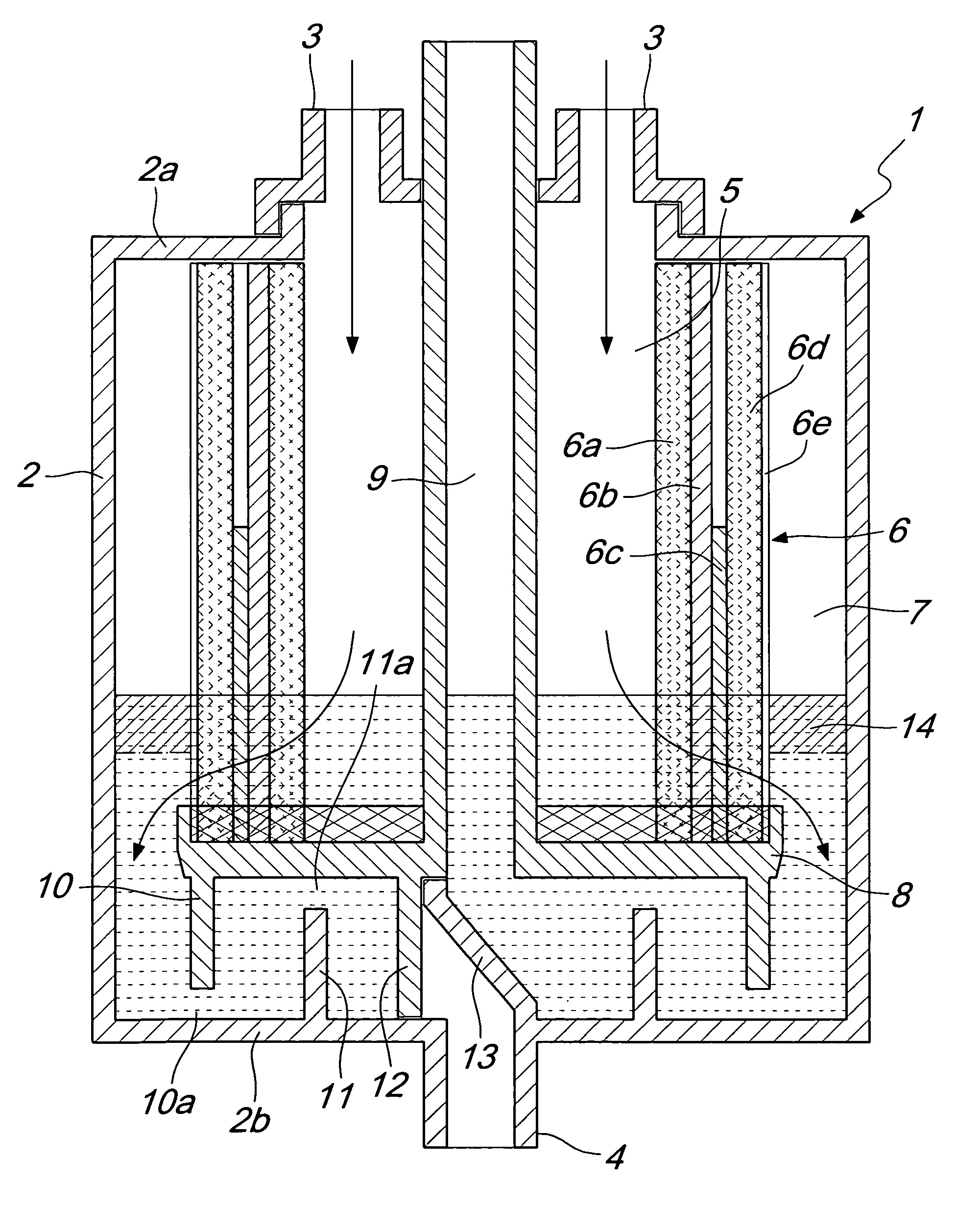
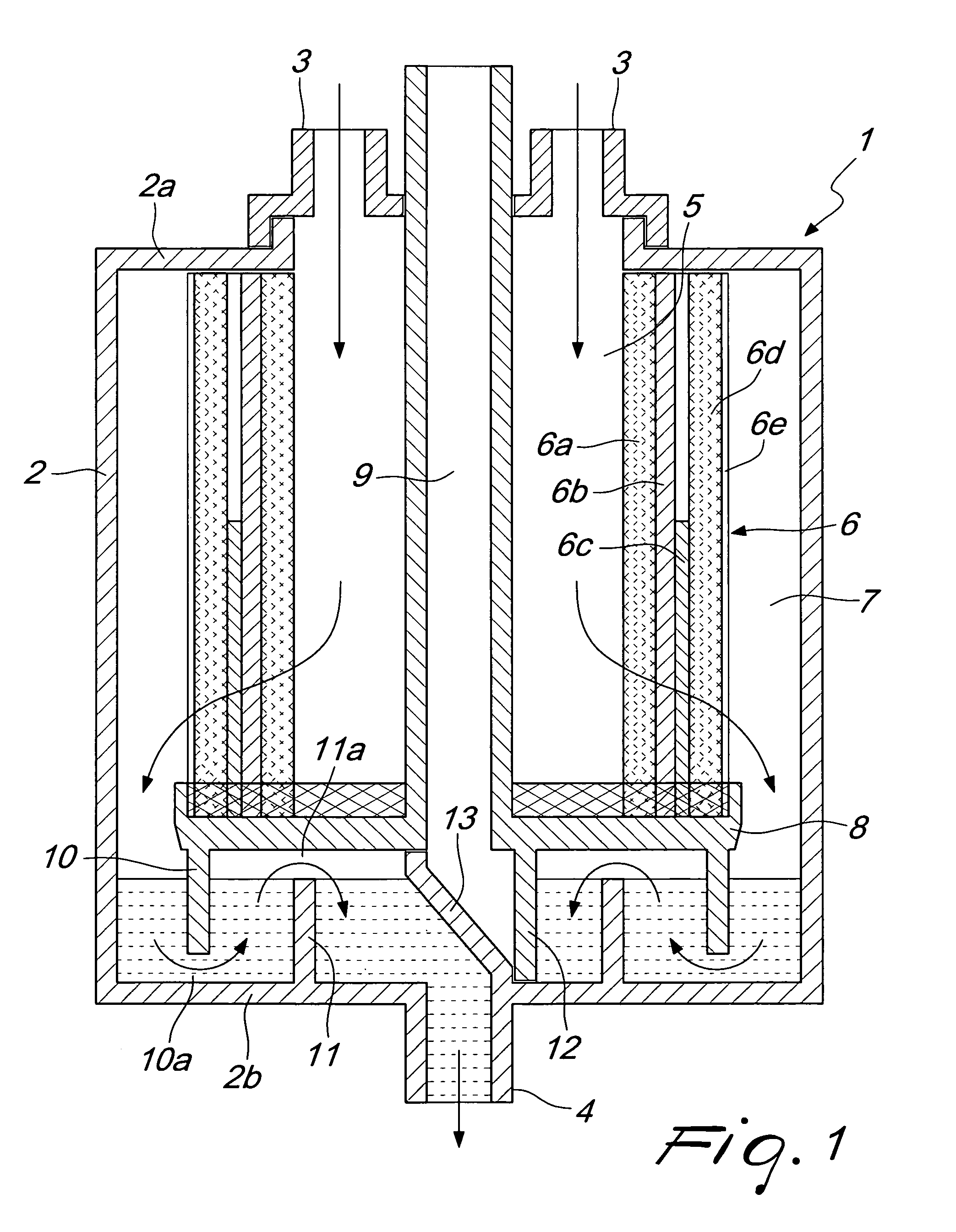
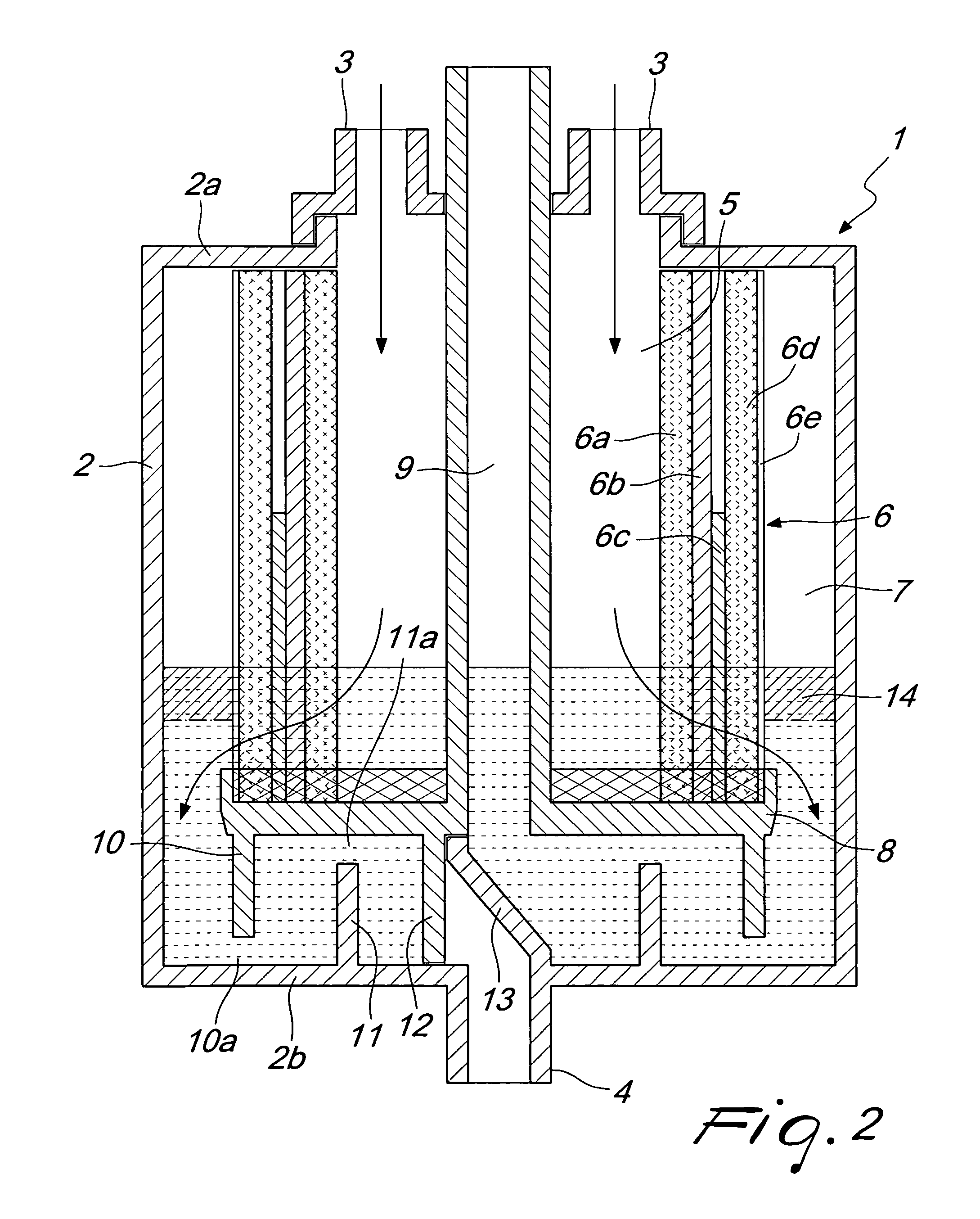
[0012]With reference to the figures, reference numeral 1 generally designates the cardiotomy reservoir, which comprises an outer wall 2 provided, at the lid 2a, with connectors 3 for the inflow of the blood to be filtered that arrives from the operating field and, at a bottom 2b, with a connector 4 for the outflow of the filtered blood.

[0013]The blood that enters the cardiotomy reservoir through the connectors 3 enters a portion of space 5, passes through a filtering mass 6 in the form of a cylinder with multiple layers, and reaches a portion of space 7 to reach, in manners specified hereinafter, the outflow connector 4, all according to the arrows shown in the figures.

[0014]More precisely, the filtering mass 6 comprises a first defoaming sponge layer 6a, a layer of non-woven fabric 6b adapted to retain fats, a layer of leukocyte filter 6c, a second layer of defoaming sponge 6d, and a containment net 6e.

[0015]The layer 6c of leukocyte filter has a rather high density and is sized w...


PUM


Abstract

A cardiotomy reservoir, comprising an outer wall provided, at the lid, with connectors for the inflow of blood to be filtered and, at the bottom, with a connector for the outflow of the filtered blood, a filtering mass being provided which divides the space delimited by the outer wall into a portion that is connected to the inflow connectors and a portion that is connected to the outflow connector; the cardiotomy reservoir comprises a layer of material adapted to retain fats present in blood, and further comprises a first partition and a second partition, which are adapted to delimit at different distances the region that comprises the blood outflow connector and are provided with ports for the passage of the blood in its path for accessing the connector which are arranged at differentiated levels with respect to the bottom, the ports that are provided in the first partition that lies closest to the outflow connector being located at a height, from the bottom, that is greater than the height of the ports provided in the second partition, detachable elements for blocking the blood outflow connector being further provided.

Description

BACKGROUND OF THE INVENTION[0001]Devices are known as cardiotomy reservoirs that are designed to receive blood collected in the operating field during surgery in order to filter it and return it to the patient after appropriate treatments.[0002]The blood that reaches the cardiotomy reservoir from the operating field may contain fats particularly derived from cuts at the sternum and at the mammary region, which can cause microemboli, with dangerous consequences, such as for example occlusion of brain arteries.[0003]Therefore, these fats must be eliminated from the blood before reinfusion to the patient, and in the background art this is done by means of a layer of non-woven fabric inserted within the filtering mass, which however operates with rather limited effectiveness.[0004]Besides to what is described above, it should be noted that there is the need to control the quantity of leukocytes in the blood, and for this purpose the background art uses a particular filtering material, k...

Claims


Application Information

Patent Timeline
Patent Type & Authority Patents(United States)
IPC IPC(8): A61M37/00
CPCA61M1/3627A61M1/3633A61M1/3695A61M1/029A61M2202/08
Inventor GHELLI, NICOLAMAIANTI, EDGARDO COSTABALANZONI, ROBERTOPETRALIA, ANTONIO
Owner EUROSETAB
Learn More