
Controller of power transmission

a control system and power transmission technology, applied in the direction of braking systems, electric propulsion mountings, gearing, etc., can solve the problems of reducing the speed of the geared transmission, the speed change operation may not be carried out in accordance with the various demands concerning the speed change operation, etc., to achieve the effect of reducing the time of the deceleration, preventing uncomfortable feeling, and minimizing the fluctuation of the deceleration

Active Publication Date: 2011-11-08
TOYOTA JIDOSHA KK
View PDF11 Cites 26 Cited by
  • Summary
  • Abstract
  • Description
  • Claims
  • Application Information

AI Technical Summary

Benefits of technology

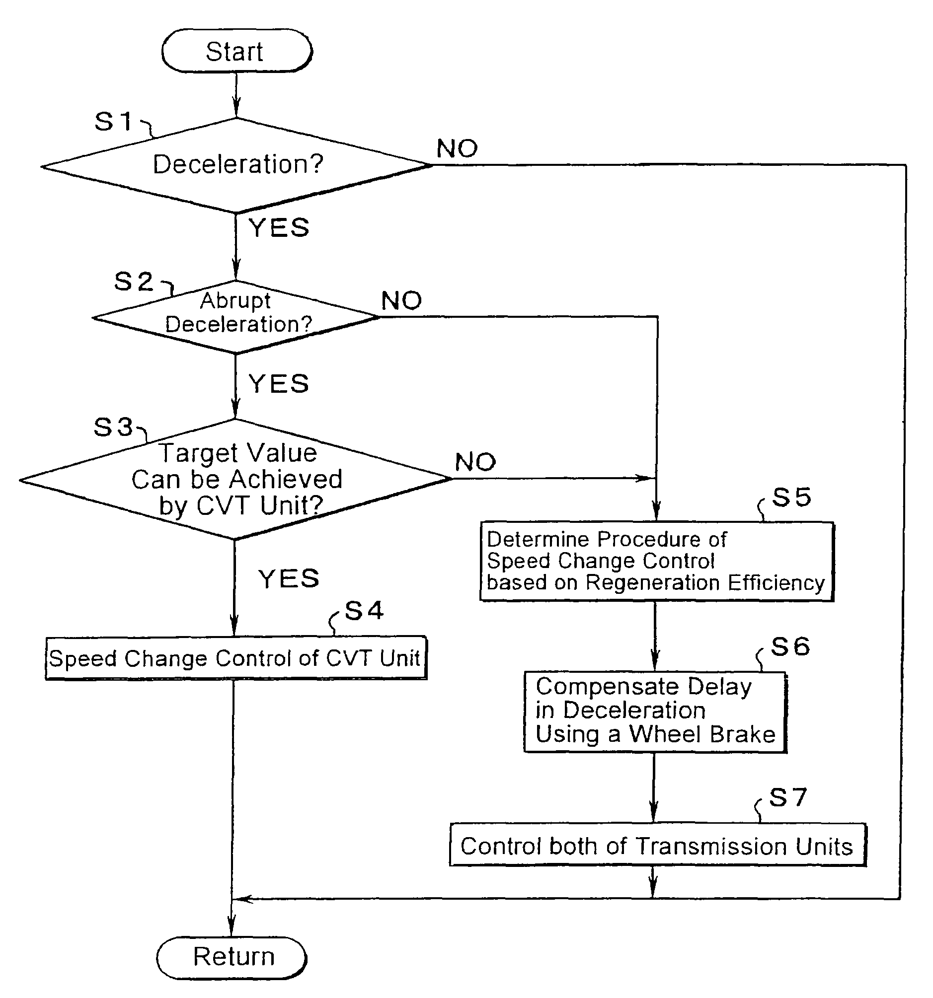
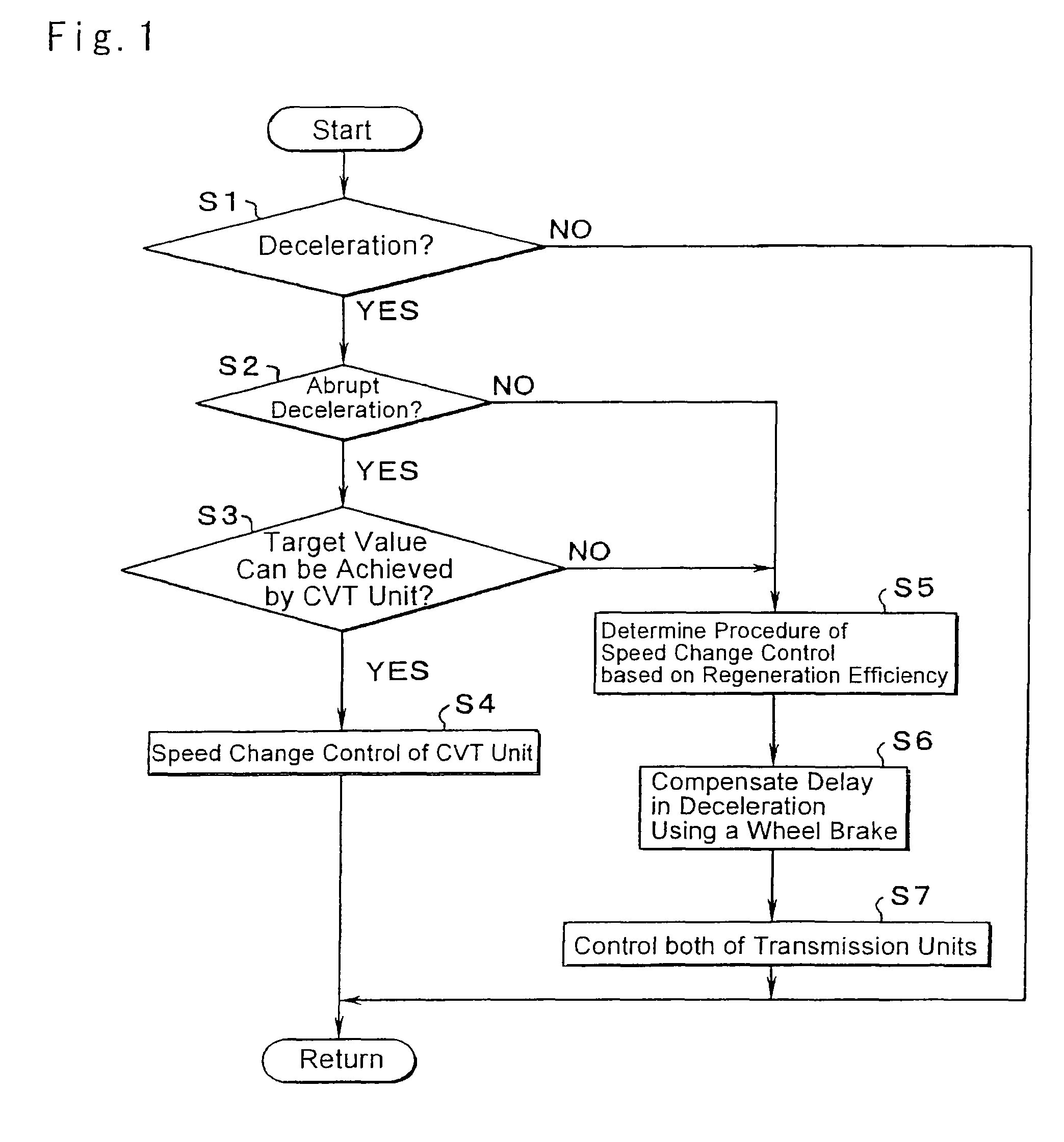
The present invention provides a control system for a power transmission system that can control a speed change operation in compliance with a speed change demand. The system includes at least two transmission units with different responsiveness to a speed change, and a speed change control means for setting a total speed change ratio by combining the speed change ratios of the transmission units. The control system can also determine the priority order of the transmission units to achieve the desired speed change. The system further includes a brake controlling means for maintaining deceleration by actuating the wheel brakes in the course of changing the speed change ratios of the transmission units. The speed change control means can also determine the combination of the speed change ratios of the transmission units based on the demanded target deceleration and the regeneration efficiency of the regeneration mechanism. The system can be mounted on a vehicle and includes a differential gear mechanism and a planetary gear mechanism for speed change. The control system can also determine the speed change ratio based on the running condition of the vehicle and the speed change diagram prepared for the vehicle.

Problems solved by technology

This means that the required time for the shifting operation of the geared transmission is relatively longer.
Therefore, if a speed change operation of the continuously variable transmission and a shifting operation of the geared transmission are always carried out on a consistent basis to approximate the total speed change ratio to the target speed change ratio, a speed change operation may not be carried out in conformity with such various demands concerning the speed change operation.

Method used


Image

  • Controller of power transmission
  • Controller of power transmission
  • Controller of power transmission

Examples


Embodiment Construction

[0043]Next, this invention will be described in connection with its specific examples. A power transmission system to which the invention is applied will be explained first of all. FIG. 4 is a skeleton diagram illustrating a transmission 10 for hybrid vehicles to which a control system as one example of the invention is applied. As illustrated in FIG. 4, the transmission 10 comprises, an input shaft 14 as an input rotary member arranged coaxially in a non-rotatable transmission case 12 (as will be called as a case 12 hereinafter) of a vehicle, an electrical continuously variable transmission unit 11 connected to the input shaft 14 directly or indirectly through a not shown pulsation absorbing damper (i.e., a vibration dampening device), a geared transmission unit 20 connected in tandem through a transmission member (i.e., a transmission shaft) 18 on a power transmission route between the continuously variable transmission unit 11 and a (not-shown) driving wheel, and an output shaft ...


PUM


Abstract

A control system for a power transmission system capable of speed change control in conformity of a deceleration demand. The transmission system includes at least two transmission units having different responsiveness to a speed change and capable of setting a speed change ratio individually, and in which a total speed change ratio is determined according to the speed change ratios of the transmission units. The control system includes a speed change control for changing a priority order to carry out a speed change operation of the individual transmission units to achieve a predetermined deceleration in conformity with a content of the deceleration demand, when the predetermined deceleration is demanded.

Description

TECHNICAL FIELD[0001]This invention relates to a control system for a power transmission system comprising a plurality of transmission units having different responsiveness to a speed change and capable of setting a speed change ratio individually.BACKGROUND ART[0002]One example of a power transmission system comprising a plurality of transmission units having different responsiveness to a speed change is disclosed in Japanese Patent Laid-Open No. 2003-127681. According to the hybrid drive system disclosed in Japanese Patent Laid-Open No. 2003-127681, an internal combustion engine is connected with a carrier of a planetary gear mechanism, and a first motor / generator is connected with a sun gear of the planetary gear mechanism. Also, a ring gear is connected with a member of an input side of a geared automatic transmission. A member of an output side of the automatic transmission is connected with a propeller shaft, and a second motor / generator is connected with the propeller shaft. ...

Claims


Application Information

Patent Timeline
Patent Type & Authority Patents(United States)
IPC IPC(8): B60K1/02B60K6/445B60K6/547B60L7/14B60T8/00B60W10/08B60W10/10B60W10/18B60W20/00F16H59/48F16H61/02F16H61/68F16H61/684F16H61/686F16H63/40F16H63/50
CPCB60K6/365B60K6/445F16H61/21B60K1/02B60W20/00Y10T477/69F16H61/686F16H2037/0866Y02T10/6239Y10T477/23Y02T10/62B60W2510/1045B60W10/11B60W20/30B60W10/105
Inventor TABATA, ATSUSHIIBARAKI, RYUJIMATSUBARA, TOORUIDESHIO, YUKIHIKOSHIBATA, HIROYUKI
Owner TOYOTA JIDOSHA KK
Learn More