Electrical connector

a technology of electrical connectors and connectors, applied in the direction of securing/insulating coupling contact members, coupling device connections, electric discharge lamps, etc., can solve the problems of increasing the manufacture cost of connectors and extra and achieve the effect of reducing manufacturing costs and economizing manpower and material resources

Inactive Publication Date: 2011-11-01
CHENG UEI PRECISION IND CO LTD
View PDF6 Cites 0 Cited by
  • Summary
  • Abstract
  • Description
  • Claims
  • Application Information

AI Technical Summary

Benefits of technology

[0007]As described above, the electrical connector of the present invention can effectively stop the solder flowing into the receiving cavity along the receiving passage, by means of the soldering slice abutting against the bottom of the connecting body, the connecting strip being propped up by the top of the propping portion, and the two oppo...

Problems solved by technology

However, it need take extra manpower and material resources to manufacture the...

Method used


Image

  • Electrical connector
  • Electrical connector
  • Electrical connector

Examples


Embodiment Construction

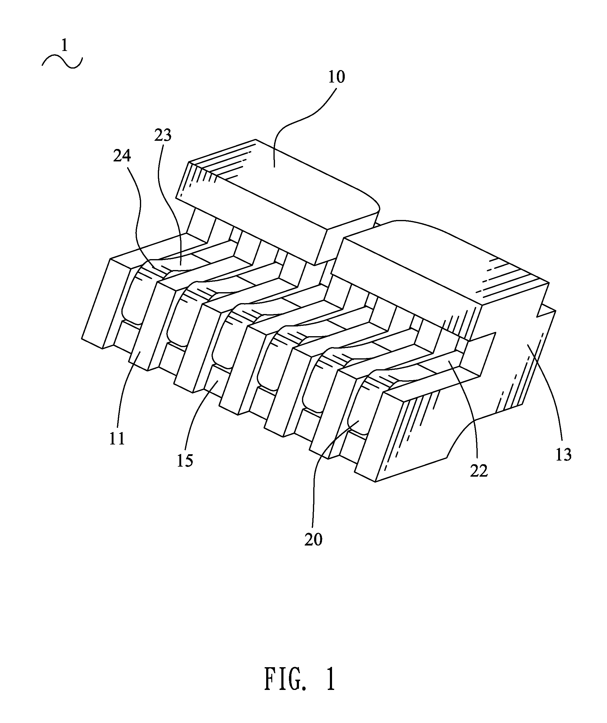
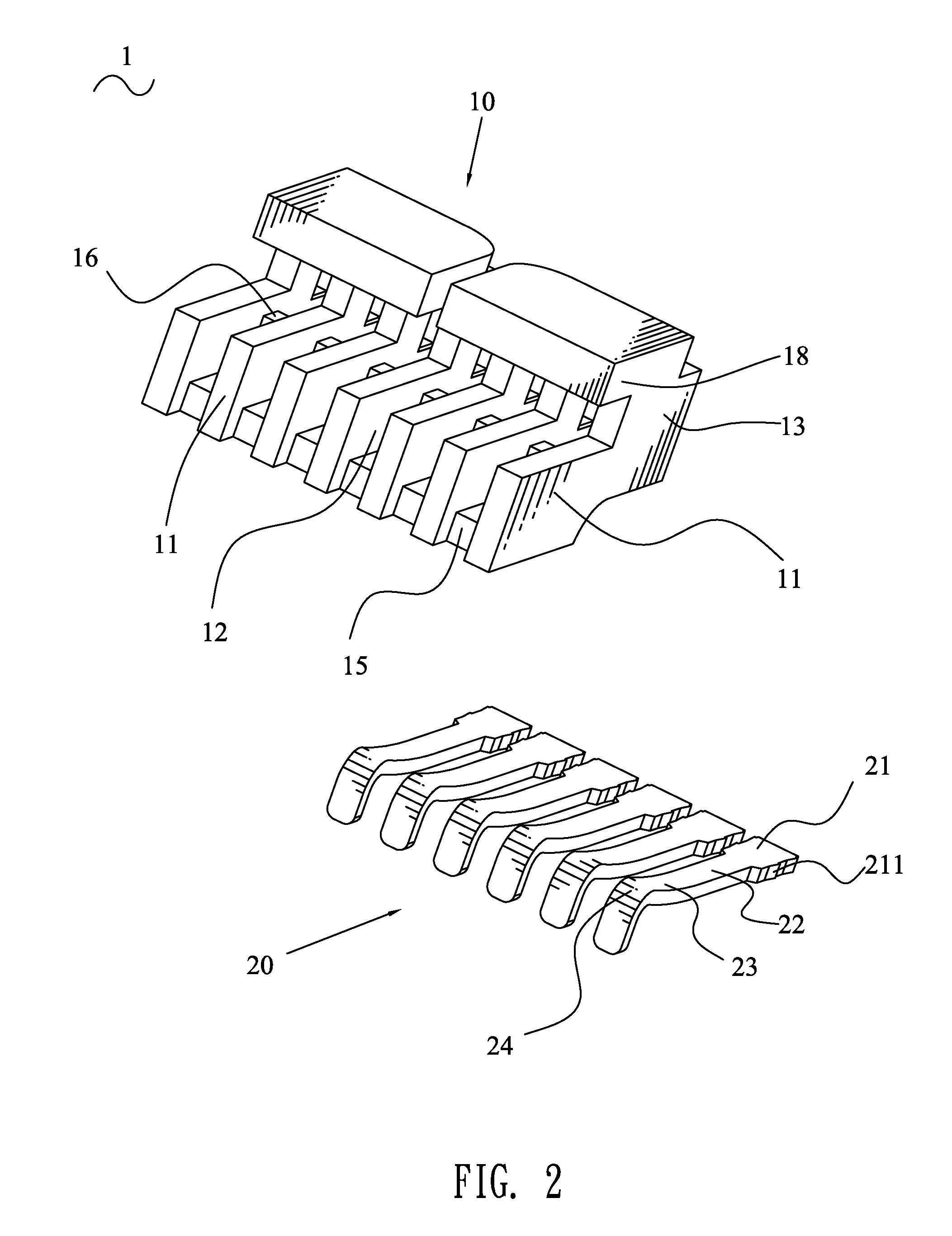
[0015]Referring to FIG. 1 and FIG. 2, an electrical connector 1 according to the present invention includes an insulating body 10 and a plurality of terminals 20 disposed in the insulating body 10 respectively.

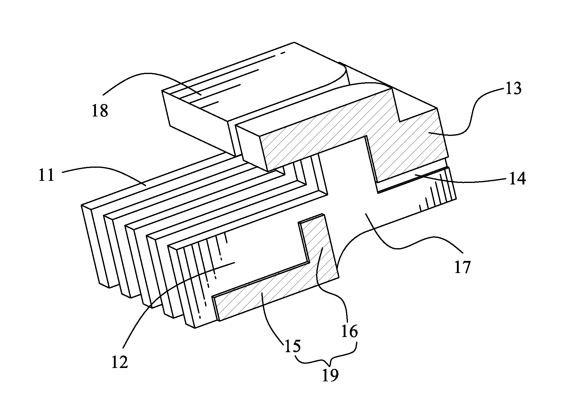
[0016]Referring to FIG. 2, FIG. 3 and FIG. 4, the insulating body 10 has a plurality of substantially rectangular base boards 11 aligned at regular intervals along a transverse direction, with each two adjacent of the base boards 11 parallel and facing to each other. An L-shaped propping member 19 is connected between fronts of the adjacent two base boards 11. The propping member 19 has a connecting portion 15 extending longitudinally, and a propping portion 16 protruding upward from a rear end of the connecting portion 15. The propping portion 16 divides the interval between the adjacent two base boards 11 into two parts, respectively designated as a receiving cavity 12 in front of the propping portion 16 and a receiving passage 17 behind the propping portion 16. The receivin...


PUM


Abstract

An electrical connector includes an insulating body which has base boards aligned at intervals along a transverse direction, propping portions each connected between adjacent two base boards to divide an interval between the adjacent two base boards into two parts designated as a receiving cavity and a receiving passage, and a connecting body traversed on rear ends of top edges of the base boards, and terminals each having a connecting strip, a soldering slice and an elastic arm oppositely extending from two ends of the connecting strip. The connecting strip and the soldering slice are disposed in the receiving passage with the soldering slice abutting against a bottom of the connecting body, the connecting strip propped up by the propping portion, and two opposite side edges of the connecting strip and the soldering slice abutting against insides of the receiving passage. The elastic arm stretches into the receiving cavity.

Description

BACKGROUND OF THE INVENTION[0001]1. Field of the Invention[0002]The present invention relates to an electrical connector, and more particularly to an electrical connector capable of stopping solder flowing forwards to damage a contact portion of a terminal thereof.[0003]2. The Related Art[0004]Referring to FIG. 5 and FIG. 6, a traditional electrical connector 2 includes an insulating body 30 and a plurality of terminals 35. The insulating body 30 has a base portion 33 and a tongue portion 31 extending forward from a middle of the base portion 33. The base portion 33 defines a plurality of fastening passages 34 arranged at regular intervals along a transverse direction thereof and each extending longitudinally to penetrate through the base portion 33. A top of the tongue portion 31 defines a plurality of receiving cavities 32 corresponding to the fastening passages 34 respectively and each extending longitudinally to be connected with a bottom of a front end of the corresponding fast...

Claims


Application Information

Patent Timeline
IPC IPC(8): H01R24/00
CPCH01R4/028H01R12/725
Inventor LIAO, WEI-HONGCHEN, MING-CHIANG
Owner CHENG UEI PRECISION IND CO LTD
Why Eureka
Try Eureka