
Asymmetrical gas turbine cooling port locations

a gas turbine and cooling port technology, applied in the direction of machines/engines, stators, liquid fuel engines, etc., can solve the problems of reduced cooling flow at joints and flanges, limited approach, thermal lag during the transient response of the machine, etc., to increase heat transfer, increase mass, and increase heat transfer

Active Publication Date: 2011-11-01
GENERAL ELECTRIC CO
View PDF5 Cites 7 Cited by
  • Summary
  • Abstract
  • Description
  • Claims
  • Application Information

AI Technical Summary

Benefits of technology

"The invention is about improving heat transfer in a turbine casing by adding bosses and flanges to the casing and creating a cooling fluid plenum around the casing. The bosses and flanges are positioned at specific locations to increase heat transfer at the joined flanges and at the first and second false flanges. The cooling fluid flows in a way that does not correspond to the horizontal and vertical symmetry planes of the casing. This design improves heat transfer and allows for better cooling of the turbine casing."

Problems solved by technology

However, the added mass from the use of false flanges typically causes a thermal “lag” during the transient response of the machine.
But the symmetrical placement of bosses and / or cooling flows has resulted in reduced cooling flows at the joints and flanges.
But this approach is limited when cooling flows are reduced due to symmetry planes.

Method used


Image

  • Asymmetrical gas turbine cooling port locations
  • Asymmetrical gas turbine cooling port locations
  • Asymmetrical gas turbine cooling port locations

Examples


Embodiment Construction

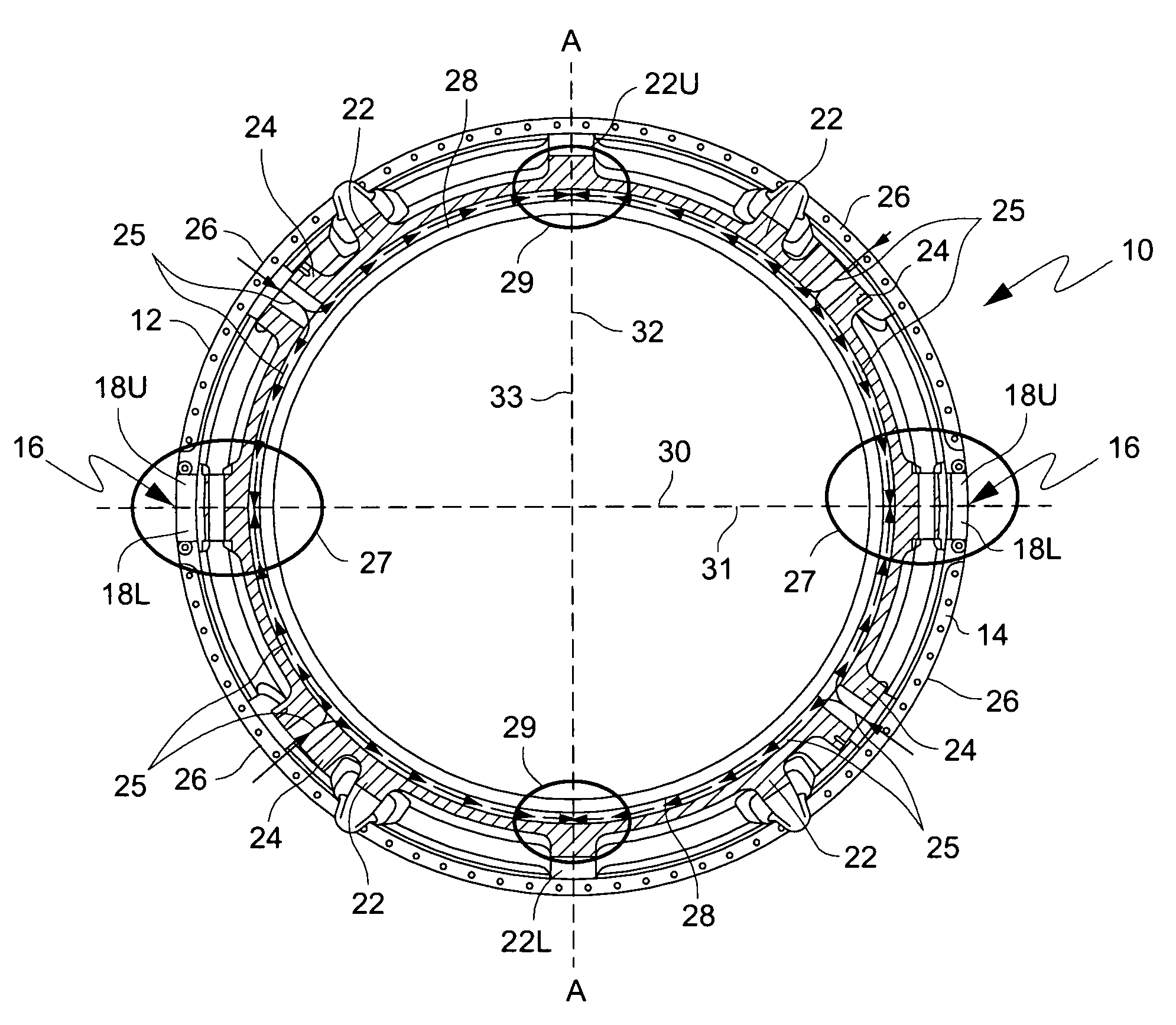
[0013]Prior art solutions to reduce out of roundness in gas turbine stator casings have used symmetrical placement of bosses and cooling flows, whereas the present invention uses asymmetrical placement of cooling flows (that can be asymmetrical in placement relative to the specific planes or in mass flow rates within a plenum) to increase heat transfer at desired locations.

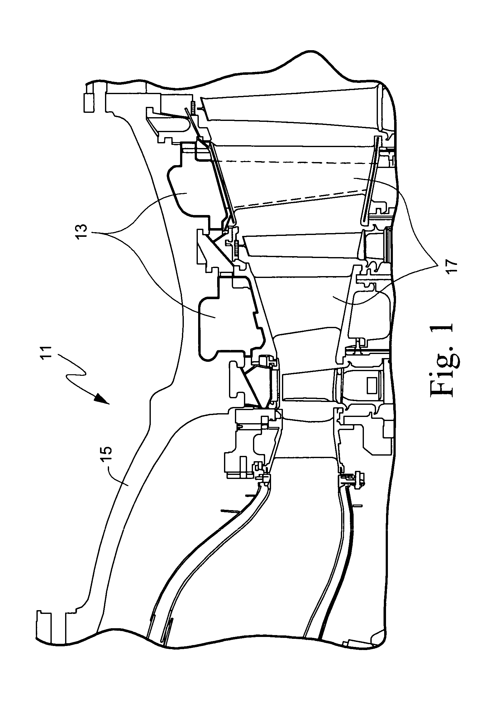
[0014]FIG. 1 is a partial cross-sectional view of a conventional gas turbine 11 showing a plenum 13 in the turbine's outer stator casing 15 for supplying cooling fluid to static nozzle guide vanes 17 attached to the turbine's outer flow path wall.

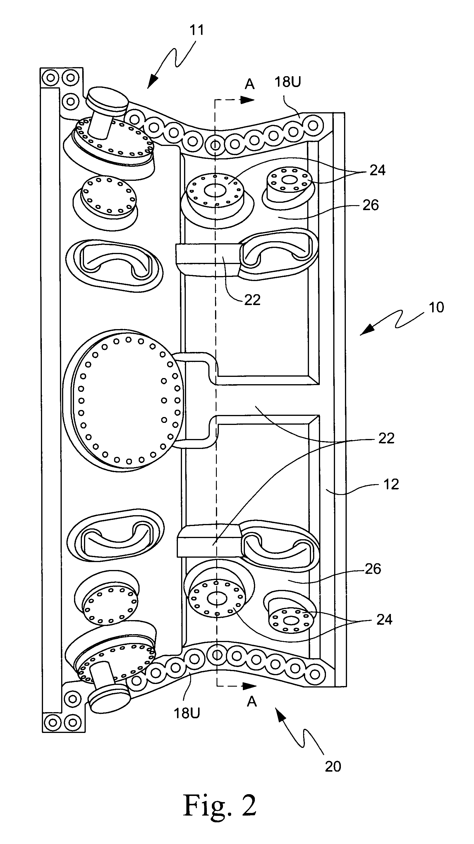
[0015]FIG. 2 is a top view of a gas turbine shell or casing 10, while FIG. 3 is a cross-sectional view of the gas turbine casing 10 taken along the line A-A in FIG. 2. As shown in FIG. 3, casing 10 is generally cylindrical in shape. Casing 10 is comprised of a semi-cylindrical upper half 12 and a semi-cylindrical lower half 14 that are joined together at horizontal split-...


PUM


Abstract

A method is disclosed for improving a turbine's thermal response during transient and steady state operating conditions in which the flow of cooling fluid in the turbine's casing is caused to be asymmetrical relative to the horizontal and vertical symmetry planes of the casing so that the turbine's cooling symmetry planes are rotated relative to its geometric symmetry planes and thereby the heat transfer at locations in the casing with increased mass is increased.

Description

[0001]The present invention relates to gas turbines, and more particularly, to a structure for and method of improving a turbine's thermal response during transient and steady state operating conditions.BACKGROUND OF THE INVENTION[0002]“Out-of-roundness” in a turbine's stator casing directly impacts the performance of the machine due to the additional clearance required between the machine's rotating and stationary parts. As clearances are reduced, machine efficiency and output increase.[0003]Turbine stator casings are typically comprised of a semi-cylindrical upper half and a semi-cylindrical lower half that are joined together at horizontal split-line joints that can have an effect on a casing's roundness. Attempts have been made to reduce the out-of-roundness effects associated with the use of horizontal joints by adding false flanges, which add mass at discrete locations, such as at the vertical plane of the casing. However, the added mass from the use of false flanges typically...

Claims


Application Information

Patent Timeline
Patent Type & Authority Patents(United States)
IPC IPC(8): F01D9/00
CPCF01D11/24F01D25/14F01D25/26F05D2240/14F05D2230/642
Inventor BLACK, KENNETH DAMON
Owner GENERAL ELECTRIC CO
Learn More