
Two-component artificial disc replacements

a technology of artificial discs and discs, applied in the field of artificial disc replacements, can solve the problems of inconvenient use, inconvenient maintenance, and inability to provide distraction across the disc space, and achieve the effects of reducing friction, high polishing, and promoting bone ingrowth

Inactive Publication Date: 2011-10-18
HOWMEDICA OSTEONICS CORP
View PDF305 Cites 9 Cited by
  • Summary
  • Abstract
  • Description
  • Claims
  • Application Information

AI Technical Summary

Benefits of technology

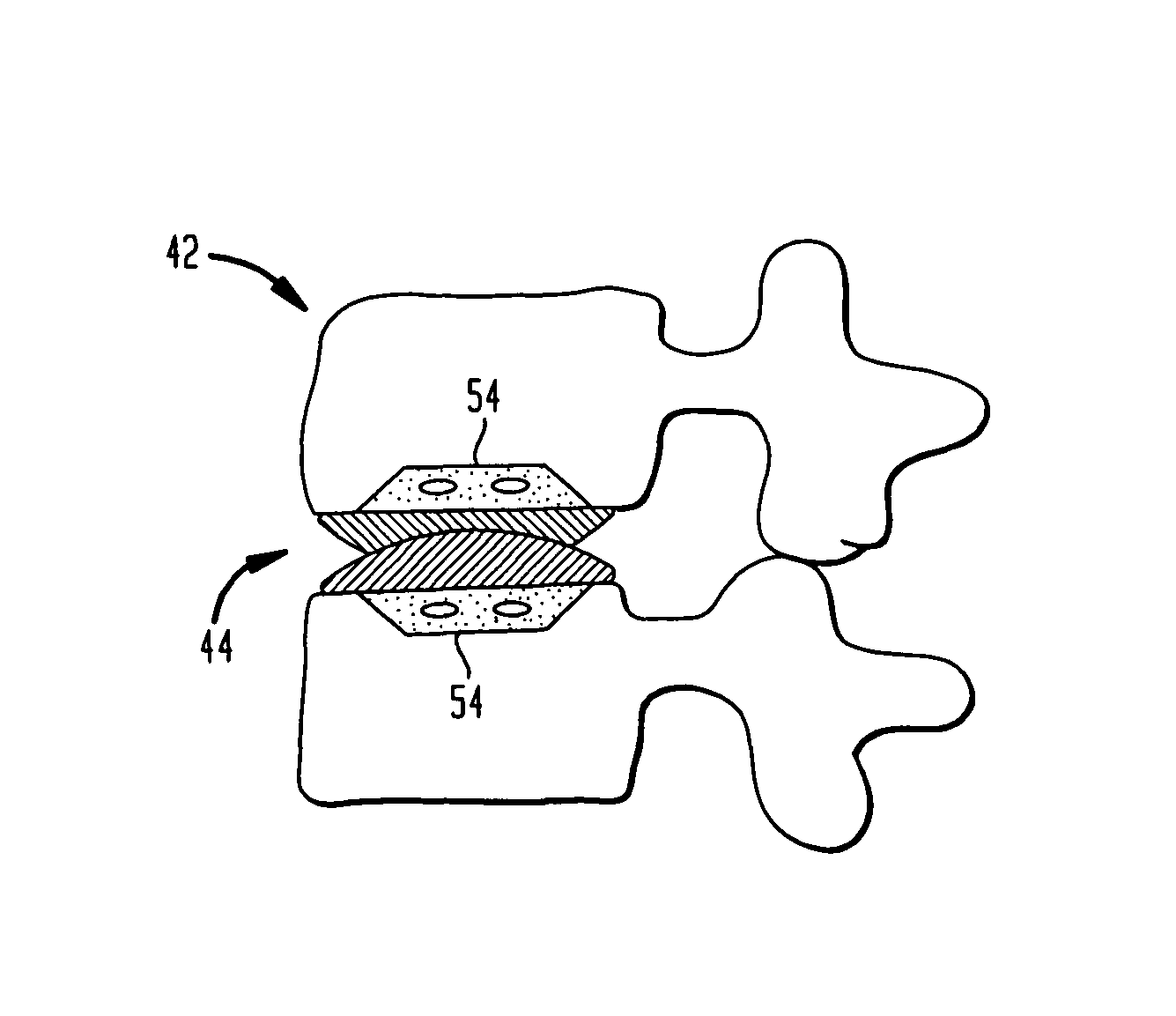
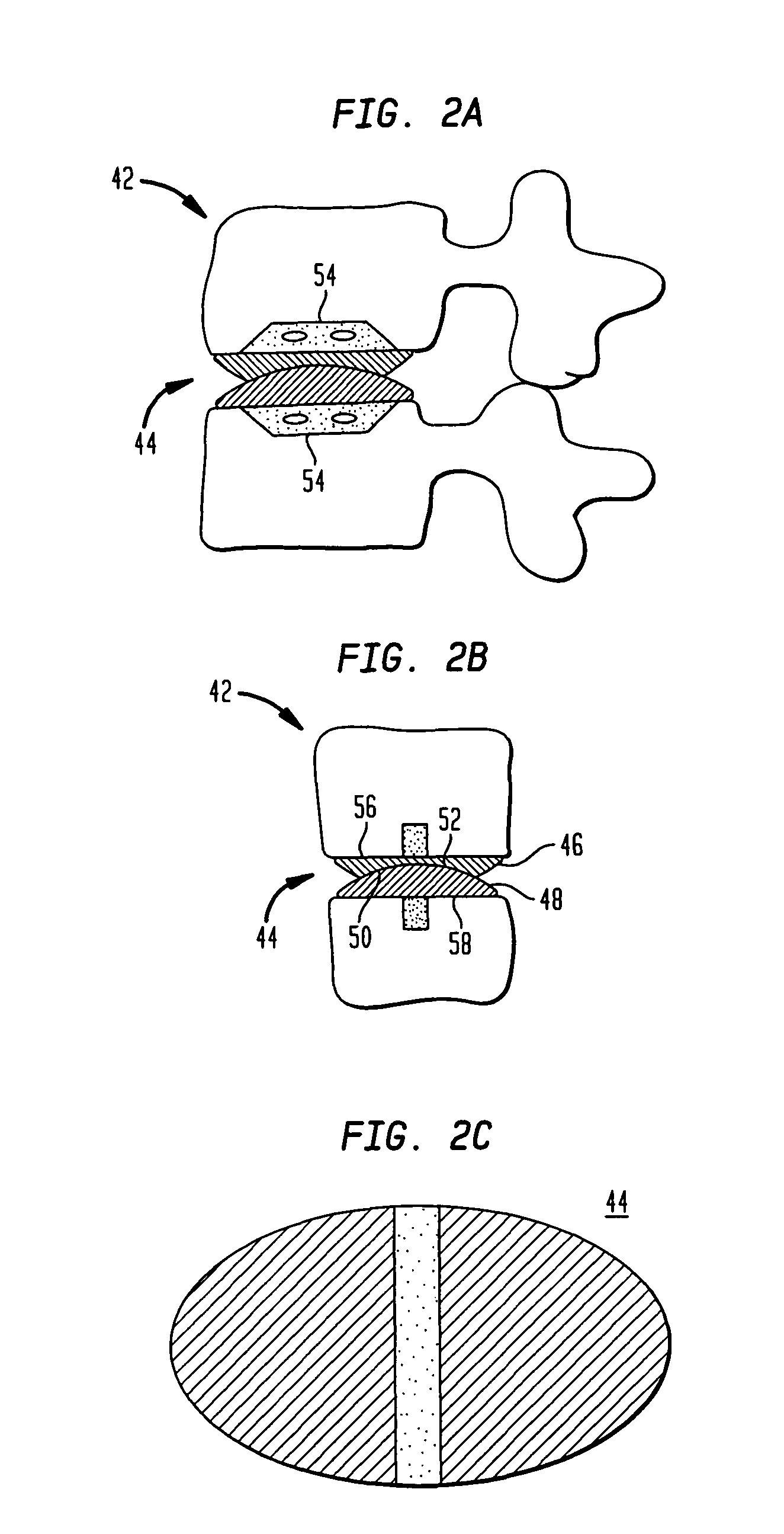
[0009]The preferred embodiment has two components, one with a concave articulating surface, and the other with a convex articulating surface. The radius of curvature of the articulating surface is smaller in the anterior to posterior direction of the ADR than radius of curvature of the articulating surface in the left to right direction of the ADR. The use of an articulating surface with two or more radius of curvature also limits axial rotation, thereby protecting the facet joints and the Annulus Fibrosus (AF). The two different radii used to create the articulating surfaces also naturally leads to an oval shape as seen from the top, which fits the oval shape of the vertebral endplate better than circularly shaped ADRs.

Problems solved by technology

Motion across arthritic facet joints could lead to pain following ADR.
In fact, bags filled with hydrogels may not provide distraction across the disc space.
Improperly aligned ADR EPs risk excessive surface wear from incongruent opposing articulating surfaces.
Furthermore, improper alignment will decrease ADR motion.
Inserting ADR EPs simultaneously limits the length of these projections, however.

Method used


Image

  • Two-component artificial disc replacements
  • Two-component artificial disc replacements
  • Two-component artificial disc replacements

Examples


Embodiment Construction

[0053]The present invention limits both facet joint pressure and facet joint motion. Broadly, the pressure on the facet joints is lowered from the preoperative pressure by distracting the disc space. The present invention also reduces the facet joint pressure by eliminating or significantly reducing motion across the ADR that increase the pressure on the facet joints. Specifically, ADR design in accordance with the various embodiments restricts spinal extension, rotation, translation, and lateral bending. Forward flexion is not restricted as forward flexion decreases the pressure on the facet joints.

[0054]FIG. 3A is a simplified drawing of a restricted motion artificial disc replacement (ADR) 40 constructed in accordance with this invention. FIG. 2A is a sagittal cross section of the spine 42 and an ADR 44 related to that shown in FIG. 3A. FIG. 2B is a coronal cross section of the spine 42 and the ADR 44 of FIG. 2A. This embodiment has two components 46, 48 one with a concave articu...


PUM


Abstract

Artificial disc replacements (ADRs) and total disc replacements (TDRs) are based upon two, directly articulating components, resulting in a restricted-motion system that better approximates more normal spinal flexion, extension, and lateral bending. One component has a concave articulating surface, and the other with a convex articulating surface. The radius of curvature of the articulating surface is smaller in the anterior to posterior direction of the ADR than radius of curvature of the articulating surface in the left to right direction of the ADR. The use of an articulating surface with two or more radius of curvature also limits axial rotation, thereby protecting the facet joints and the Annulus Fibrosus (AF). The two different radii used to create the articulating surfaces also naturally leads to an oval shape as seen from the top, which better fits the oval shape of the vertebral endplate better than circularly shaped ADRs. Both components are preferably made of a hard material and are highly polished to reduce friction.

Description

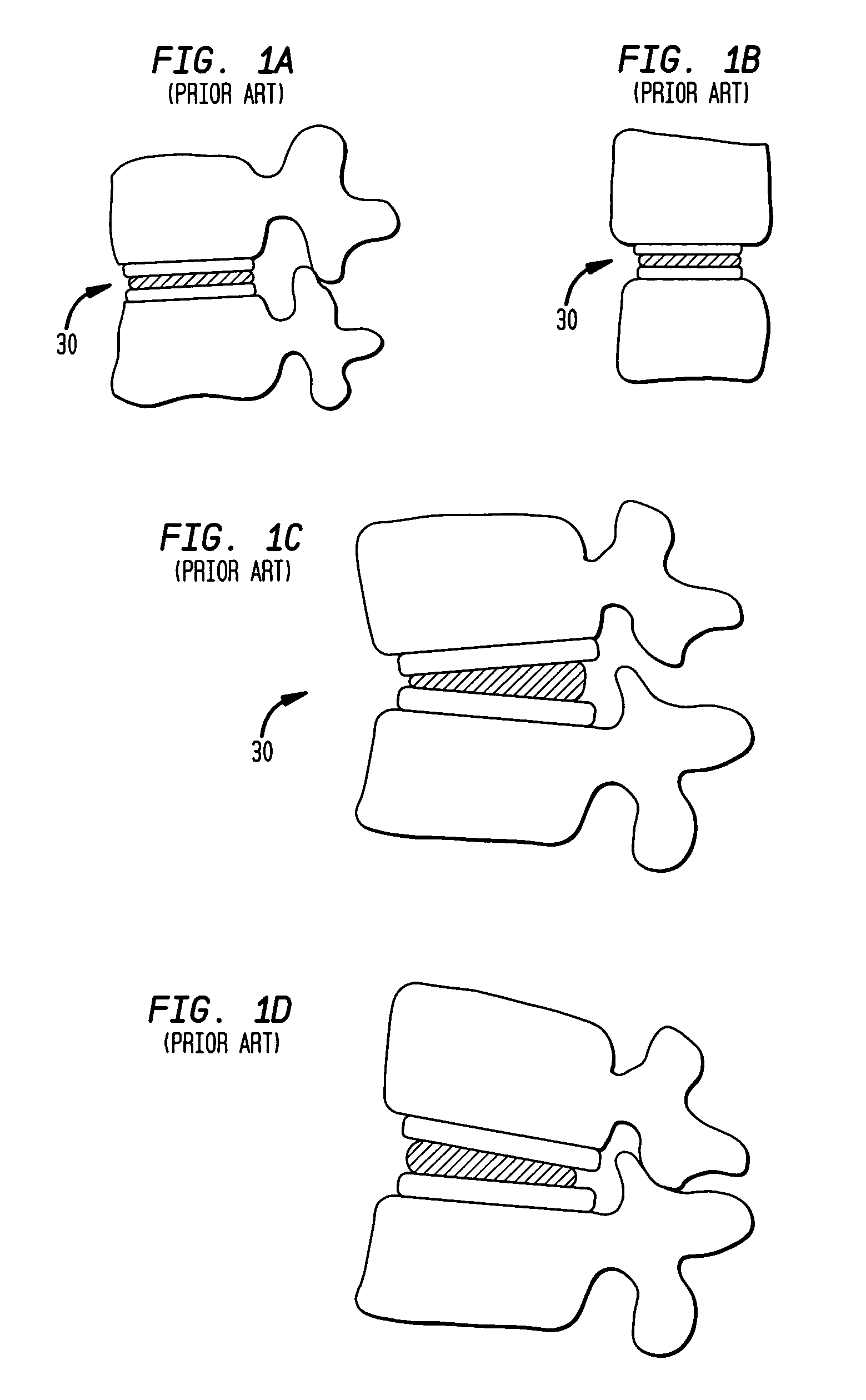
CROSS-REFERENCE TO RELATED APPLICATIONS[0001]This application claims priority from U.S. Provisional Patent Application Ser. No. 60 / 374,747, filed Apr. 23, 2002; and is a continuation-in-part of U.S. patent application Ser. No. 10 / 413,028 entitled “Spacerless Artificial Disc Replacements,” filed Apr. 14, 2003, the entire content of both applications is incorporated herein by reference.FIELD OF THE INVENTION[0002]This invention relates generally to artificial disc replacements (ADRs) and total disc replacements (TDRs) and, more particularly, directly articulating replacements based on two components.BACKGROUND OF THE INVENTION[0003]Many spinal conditions, including degenerative disc disease, can be treated by spinal fusion or artificial disc replacement (ADR). ADR has several advantages over spinal fusion. The most important advantage of ADR is the preservation of spinal motion. Spinal fusion eliminates motion across the fused segments of the spine. Consequently, the discs adjacent to...

Claims


Application Information

Patent Timeline
IPC IPC(8): A61F2/44A61F2/00A61F2/30
CPCA61F2/442A61F2/4425A61F2/30767A61F2002/3008A61F2002/30507A61F2002/30563A61F2002/30578A61F2002/30604A61F2002/30649A61F2002/30769A61F2002/30841A61F2002/30884A61F2002/30919A61F2002/443A61F2220/0025A61F2250/0098A61F2310/00023A61F2310/00029A61F2310/00203A61F2310/00239A61F2310/00293
Inventor FERREE, BRET A.
Owner HOWMEDICA OSTEONICS CORP
Learn More