
Image forming apparatus

a technology of image forming apparatus and printing mechanism, which is applied in the field of printing machine, can solve the problems of not being able to fully use the productivity of the printing mechanism to output the print sheets, affecting the productivity of the printer, and no print sheet is transferred

Active Publication Date: 2011-10-18
RISO KAGAKU CORP
View PDF13 Cites 9 Cited by
  • Summary
  • Abstract
  • Description
  • Claims
  • Application Information

AI Technical Summary

Benefits of technology

The present invention relates to an image forming apparatus that can properly perform forward-reverse control in a sheet reversing mechanism to achieve the output of print sheets at a productivity level achievable by a printing mechanism. The technical effect of the invention is to ensure that the sheet reversing mechanism can start acceleration from a stopped state to the transfer speed required for printing, and to control the sheet reversing mechanism so as to not cause a difference in speed from other sheet transfer mechanisms concurrently transferring the same print sheet. Additionally, the invention provides a method for detecting the presence or absence of a print sheet and controlling the sheet reversing mechanism accordingly to ensure proper preparation for the next print sheet.

Problems solved by technology

Thus, a circulating transfer speed by the transfer mechanism affects the productivity of the printer.
Specifically, an inappropriate circulating transfer speed causes a situation where no print sheet is transferred to the printing mechanism which is ready to perform printing.
Thus, the productivity of the printing mechanism can not be fully used to output the print sheets.
When this preparation is delayed, sheet transfer is not smoothly performed and thus a proper circulating transfer speed cannot be achieved.
Such a difference in speed may adversely affect the sheet transfer.

Method used


Image

  • Image forming apparatus
  • Image forming apparatus
  • Image forming apparatus

Examples


Embodiment Construction

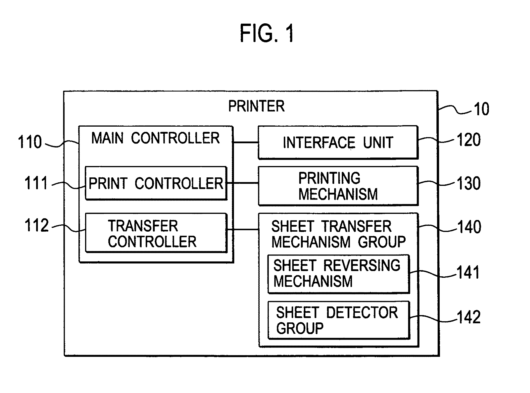
[0034]With reference to the drawings, an embodiment of the present invention will be described in detail. FIG. 1 is a block diagram showing a main functional configuration of a printer 10 according to an embodiment of the present invention. As shown in FIG. 1, the printer 10 includes a main controller 110, an interface unit 120, a printing mechanism 130 and a sheet transfer mechanism group 140.

[0035]The main controller 110 consists of a CPU, a memory, an image processing device and the like, and performs control of various kinds of processing in the printer 10 by operating the CPU according to programs stored in the memory, and by operating in other ways. In this embodiment, the main controller 110 includes a print controller 111 configured to control the printing mechanism 130 and a transfer controller 112 configured to control the sheet transfer mechanism group 140.

[0036]The interface unit 120 receives print data from an unillustrated computer network connected thereto and perform...


PUM

PropertyMeasurementUnit
transfer speed Vraaaaaaaaaa
lengthaaaaaaaaaa
length Lyaaaaaaaaaa

Abstract

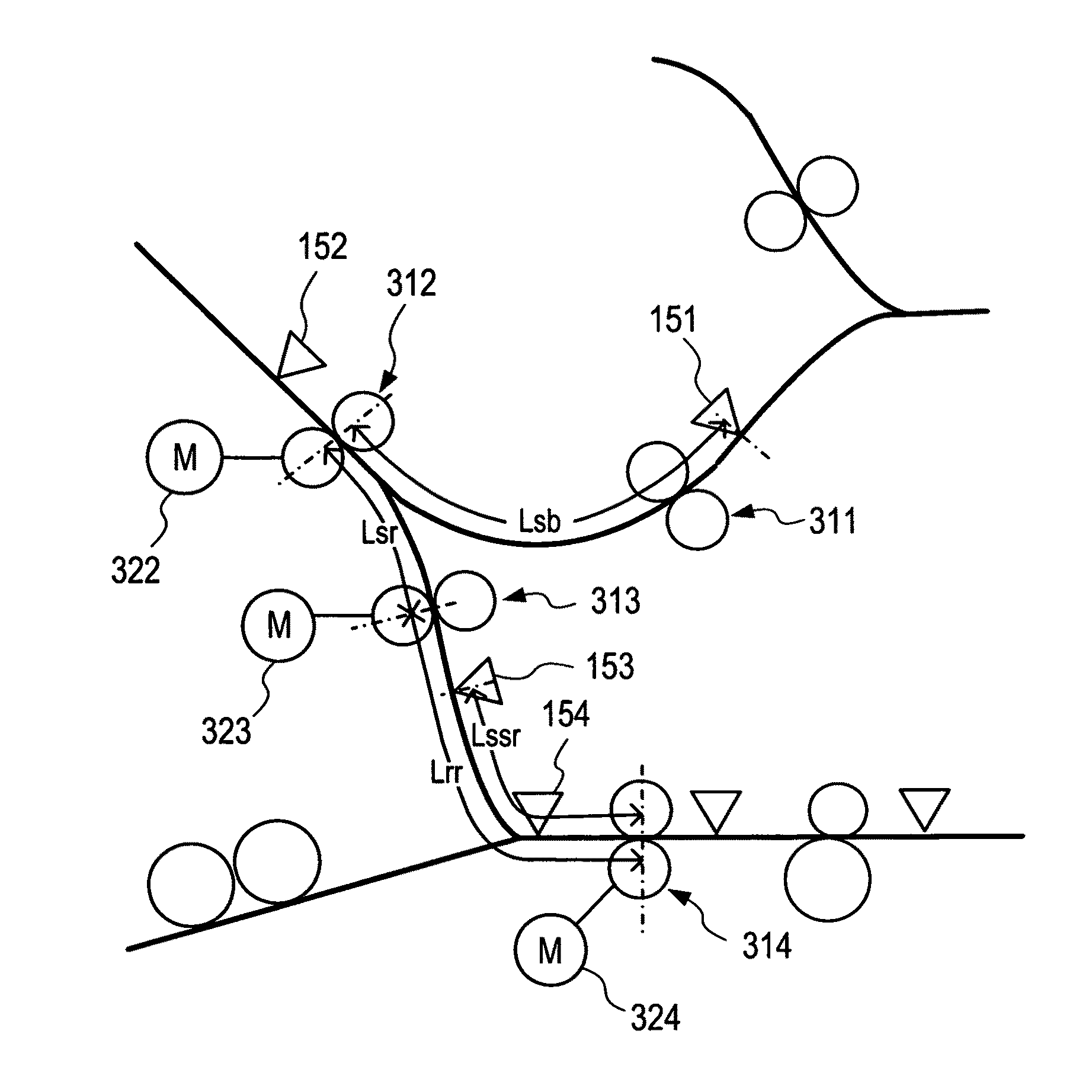
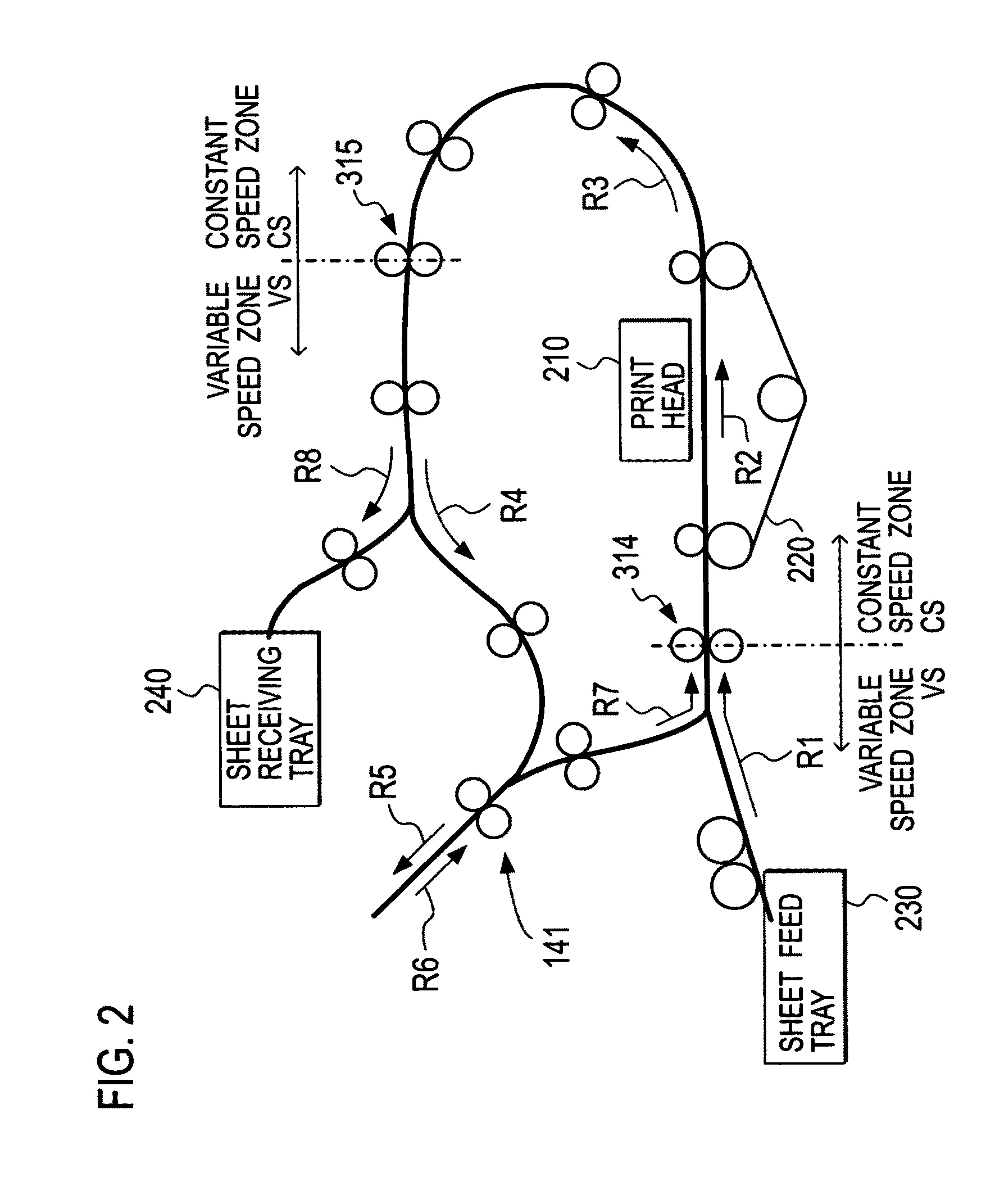
In an image forming apparatus, a sheet reversing mechanism is configured to take over and transfer, at a transfer speed Vr, a print sheet with an image already formed on one side being transferred at the transfer speed Vr from a first transfer mechanism, to stop the print sheet once, then to start transfer of the print sheet in an opposite direction, and to pass the print sheet to a second transfer mechanism at the transfer speed Vr. The first and second transfer mechanisms are located on upstream and downstream of a switchback reverse path for reversing print sheets respectively Upon lapse of a time T1 after detection of the print sheet by a print sheet detection unit, a transfer control unit drives the sheet reversing mechanism to start acceleration from a stopped state to the transfer speed Vr, the time T1 calculated based on the transfer speed Vr.

Description

CROSS REFERENCE TO RELATED APPLICATION[0001]This application is based upon and claims the benefit of priority from the prior Japanese Patent Application No. 2009-035651, filed on Feb. 18, 2009, the entire contents of which are incorporated herein by reference.BACKGROUND OF THE INVENTION[0002]1. Field of the Invention[0003]The present invention relates to a printer, and more specifically to an image forming apparatus including a circulating transfer path having a sheet reversing mechanism.[0004]2. Description of the Related Art[0005]There has been known a double-sided printer which has a circulating transfer path including a sheet reversing mechanism and which reverses a sheet printed on one side to perform printing on the other side. There has recently been an increasing demand that a printer should have an improved productivity with faster printing speed. To achieve this, the printer is required to perform not only single-side printing but also double-side printing at a high produc...

Claims


Application Information

Patent Timeline
Patent Type & Authority Patents(United States)
IPC IPC(8): B65H29/00
CPCB65H5/26B65H7/02B65H2301/33214B65H2301/3331B65H2511/51B65H2513/21B65H2513/514B65H2513/53B65H2220/01B65H2220/02B65H2220/03B65H2513/20B65H2513/512B65H2513/52
Inventor HARA, MASASHI
Owner RISO KAGAKU CORP
Learn More