
Eddy current braking system for trolley zip line cable

a technology of eddy current and trolley zip line, which is applied in the direction of asynchronous induction clutch/brake, mechanical equipment, transportation and packaging, etc., can solve problems such as falling onto the track, and achieve the effect of increasing the drag valu

Inactive Publication Date: 2011-10-18
BOREN DANIEL
View PDF25 Cites 46 Cited by
  • Summary
  • Abstract
  • Description
  • Claims
  • Application Information

AI Technical Summary

Benefits of technology

[0023]Another object of the present invention is to provide a magnetic braking system that as the magnetic field increases the drag value also increases.
[0025]Still yet another object of the present invention is to provide a magnetic braking system comprising a trolley having a conductive member attached thereto that is driven into a magnetic field causing eddy currents which will retard movement of the conductive member within the magnetic field and thereby bring the attached trolley to a stop.
[0027]Yet another object of the present invention is to provide an alternate magnetic braking system having the conductive member fastened by cable to a brake block positioned within the path of the trolley so that when engaged by the trolley the conductive member is driven into the magnetic field creating an eddy current that slows the trolley to a stop. As the magnetic field increases the drag value also increases.
[0029]The present invention overcomes the shortcomings of the prior art by providing a magnetic braking system that is based on drag created when a conductor moves through a magnetic field. As the magnetic field increases the drag value also increases. The invention provides a magnetic braking system for use on zip line / cable rides and trolleys.

Problems solved by technology

The brake is held clear of the rail in normal running of the train, but may fall onto the track if its support is damaged or breaks.

Method used


Image

  • Eddy current braking system for trolley zip line cable
  • Eddy current braking system for trolley zip line cable
  • Eddy current braking system for trolley zip line cable

Examples


Embodiment Construction

[0058]The following discussion describes in detail one embodiment of the invention (and several variations of that embodiment). This discussion should not be construed, however, as limiting the invention to those particular embodiments, practitioners skilled in the art will recognize numerous other embodiments as well. For definition of the complete scope of the invention, the reader is directed to appended claims.

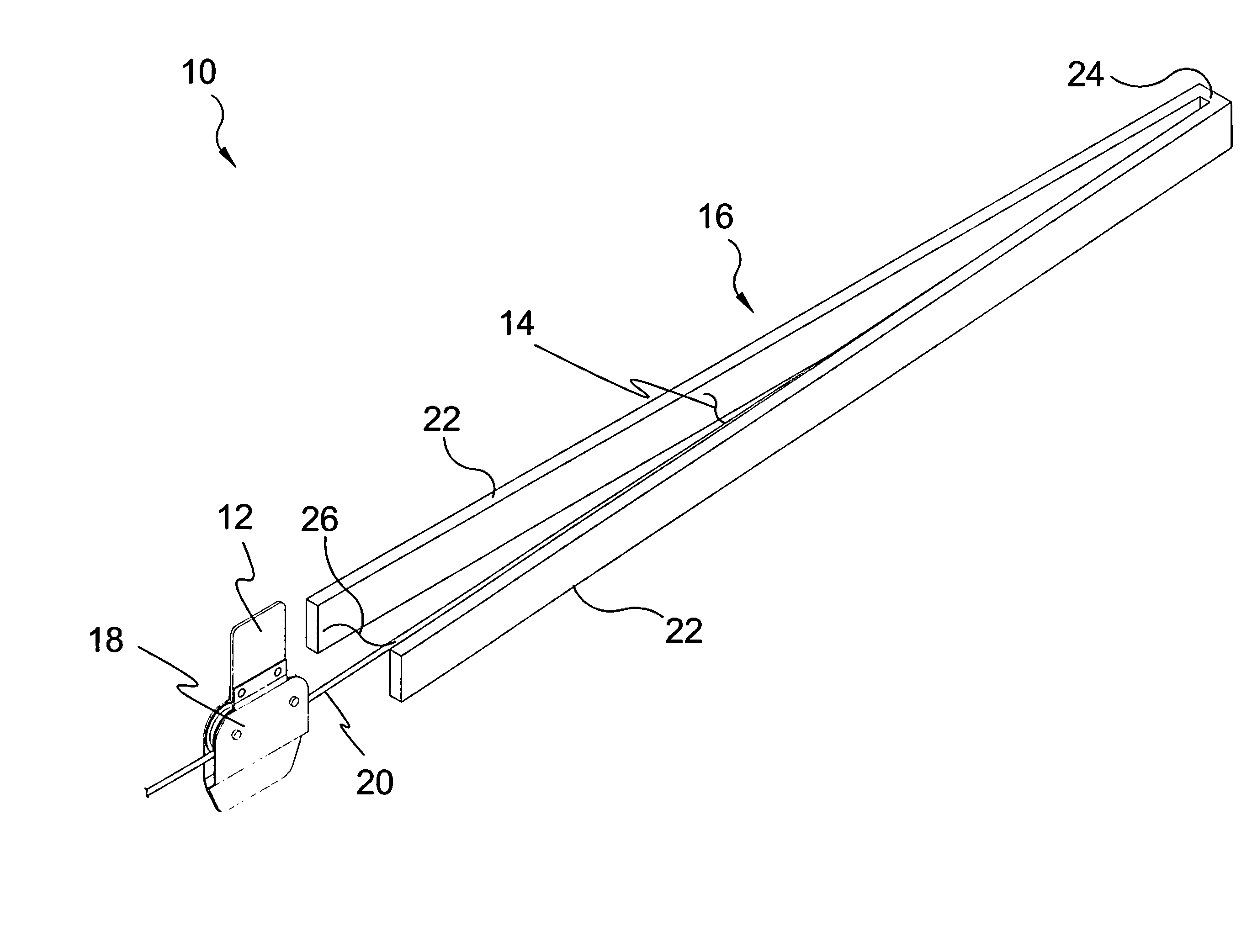
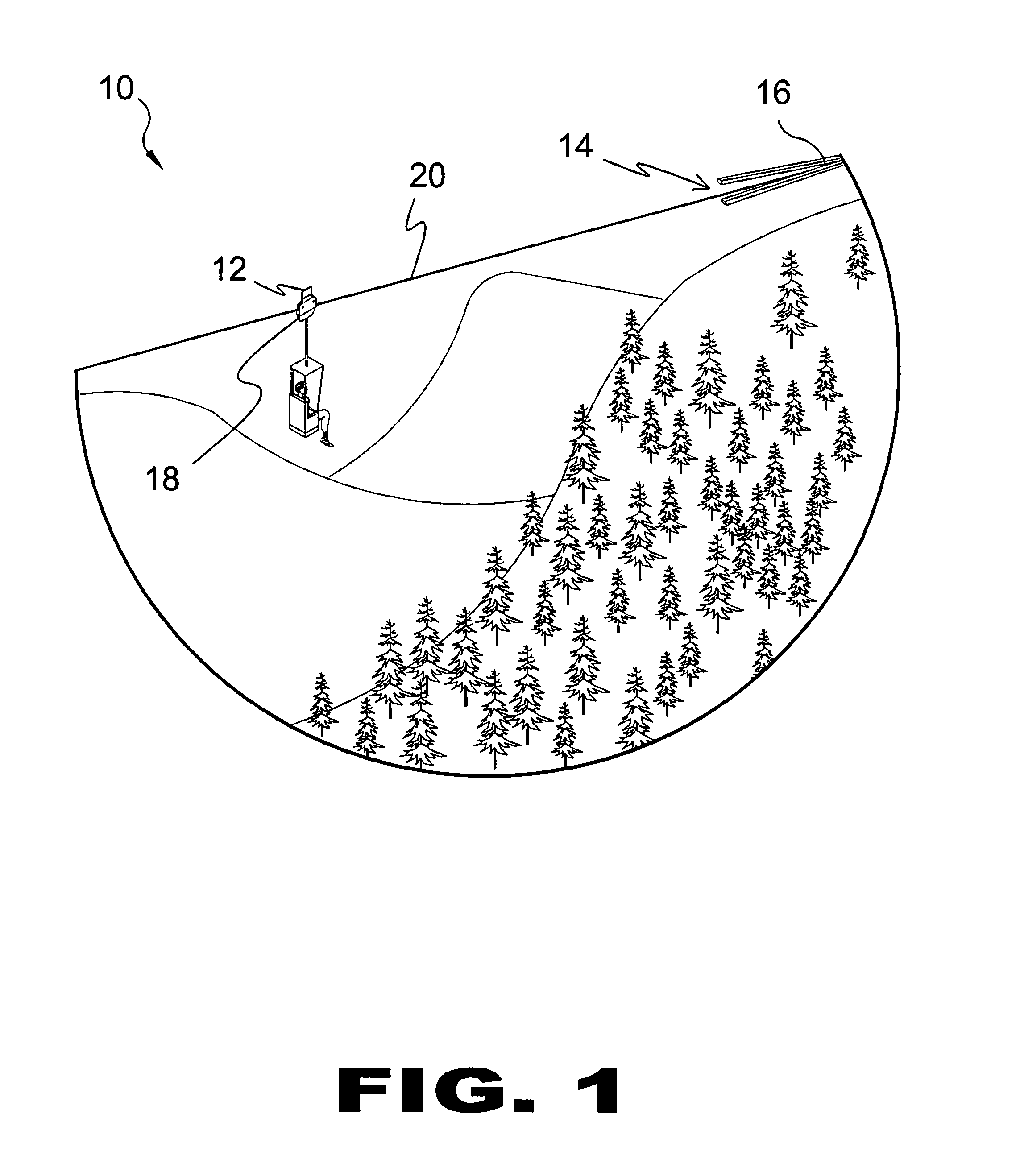
[0059]FIG. 1 is an illustrative view of the present invention 10 in use. The present invention is based on drag created when a conductor plate 12 moves through a magnetic field 14 created by a fixed, stationary magnetic field generator 16. As the magnetic field 14 increases the drag value also increases. The invention provides a magnetic braking system for use on zipline / cable 20 rides and trolley 18.

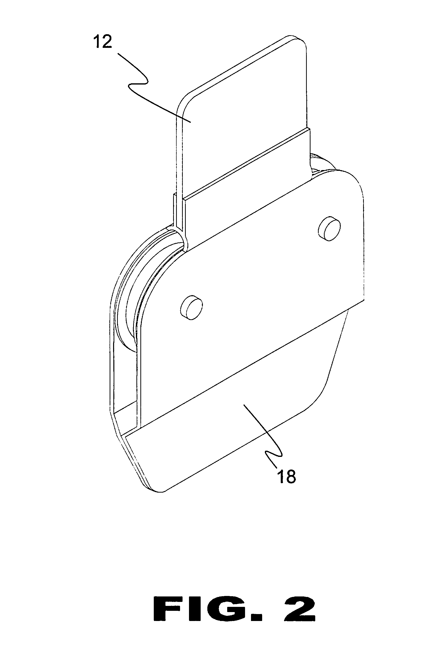
[0060]FIG. 2 is a perspective view of a trolley 18 of the present invention. Shown is the trolley 18 of the present invention having a conductor plate 12 that moves through a ...


PUM


Abstract

An eddy current magnetic braking system that is based on drag created when a conductor moves through a stationary magnetic field. As the magnetic field increases the drag value also increases. The invention provides a magnetic braking system for use on zip line / cable rides and trolleys. Alternate designs of the present invention include a magnetic braking system having a trolley that moves on a zip line / cable to a brake block which is connected to a pulley cable, as the trolley pushes the brake block, the pulley moves the conductor into a magnetic field creating an eddy current brake that slows the trolley to a stop.

Description

BACKGROUND OF THE INVENTION[0001]1. Field of the Invention[0002]The present invention relates generally to brake systems and, more specifically, to a trolley magnetic braking system comprising a magnetic member having a base with diverging arms having magnetic elements fixed thereto providing opposing spaced apart magnetic fields and a trolley mechanism having a conductive element fastened thereto and outwardly depending therefrom that is driven into the converging magnetic fields creating eddy currents that retard movement of the conductive element and attached trolley mechanism creating a braking system having no moving parts.[0003]Alternate designs of the present invention include a magnetic braking system wherein the conductive member is removed from the trolley and attached via a zipline / cable to a brake block so that the trolley will engage the brake block at a predetermined point driving the cable attached conductive member into the magnetic field slowing the trolley to a sto...

Claims


Application Information

Patent Timeline
Patent Type & Authority Patents(United States)
IPC IPC(8): F16D65/36F16D65/28
CPCH02K49/04
Inventor BOREN, DANIEL
Owner BOREN DANIEL
Learn More