
Electrowetting display device

a display device and display screen technology, applied in the field of electrowetting display devices, can solve the problems of failure to achieve full black display, design may cease to function, design color saturation is inferior, etc., and achieves the effect of increasing color saturation and simplifying fabrication processes

Inactive Publication Date: 2011-10-11
WINTEK CORP
View PDF14 Cites 15 Cited by
  • Summary
  • Abstract
  • Description
  • Claims
  • Application Information

AI Technical Summary

Benefits of technology

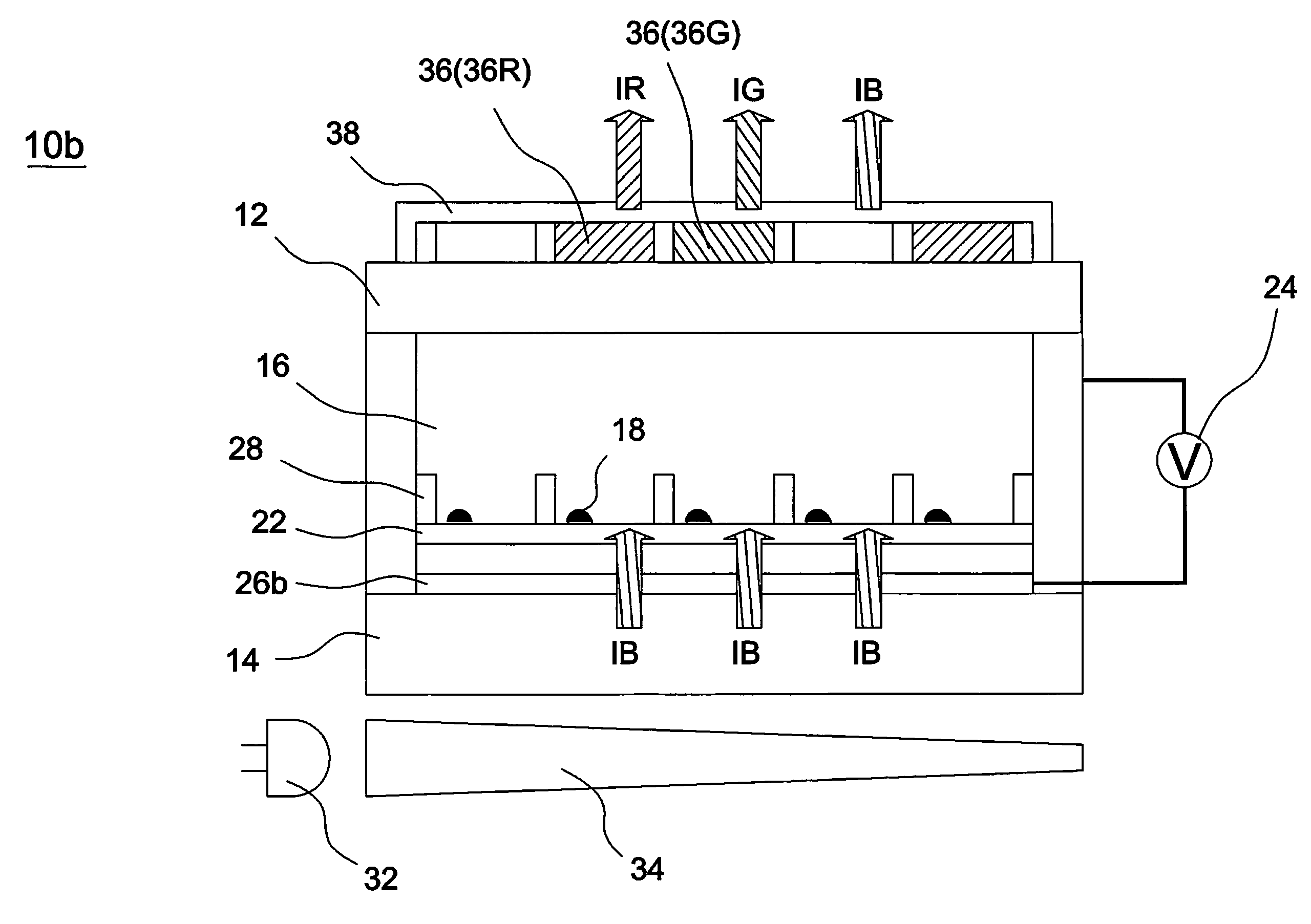
"The invention is a full-color electrowetting display device that uses a luminescence conversion mechanism to achieve excellent color saturation. The device includes a plurality of pixel units divided by partition walls, with a polar liquid and a non-polar liquid present in each unit. A phosphor layer is formed on one of the substrates and receives short-wavelength light incident to the display device. The phosphor layer comprises a first part that transforms the short-wavelength light into a first light, a second part that transforms the short-wavelength light into a second light, and a third part that allows the short-wavelength light to pass therthrough without transformation. The first, second, and third parts are corresponding to one pixel unit. The use of short-wavelength light as a light source for fluorescence excitation allows for the obtainment of different wavelengths of visible light, resulting in full-color display with improved color saturation. The invention simplifies fabrication processes and avoids the mix of surrounding white light or other colored light to achieve full-black display."

Problems solved by technology

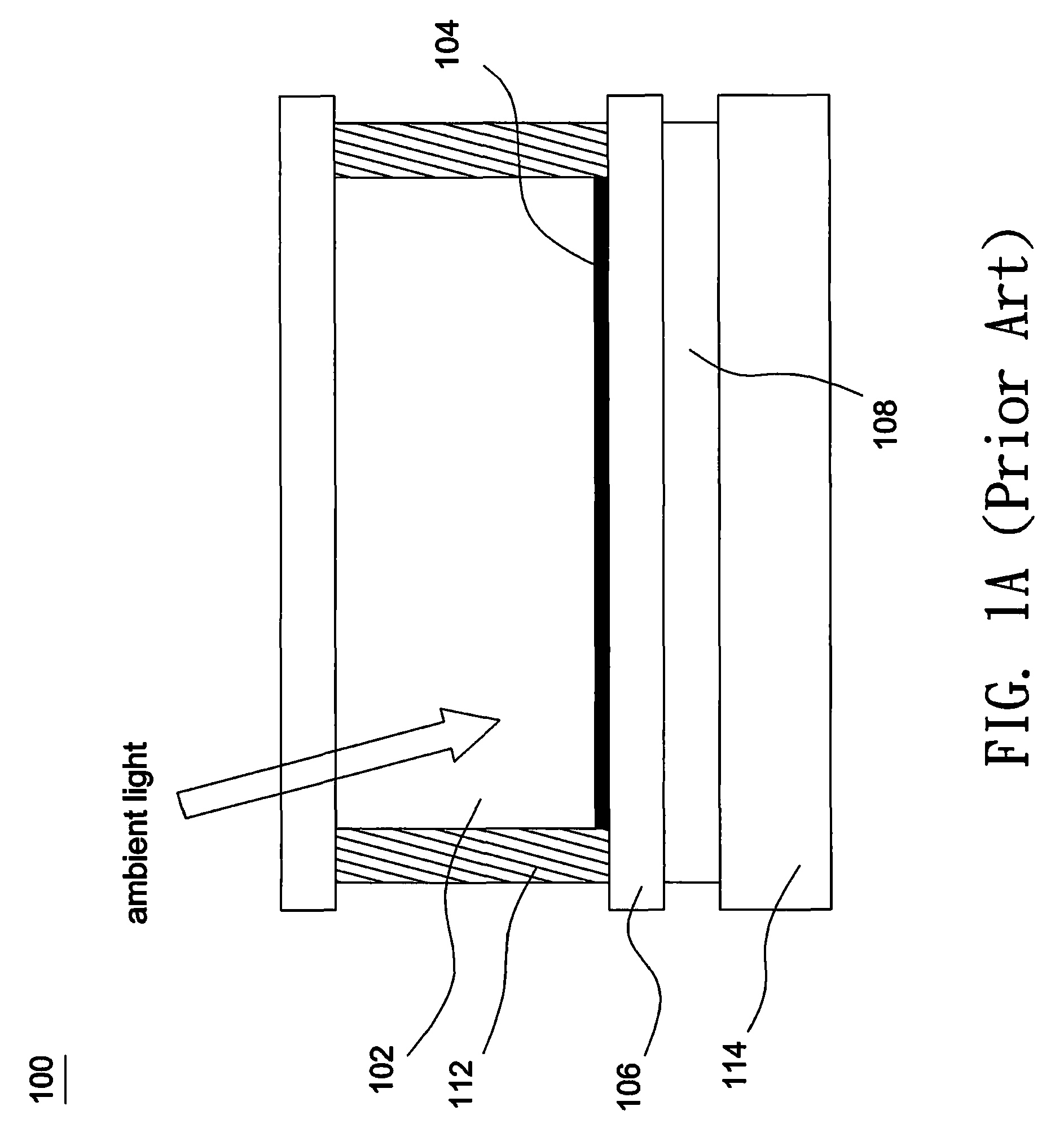
However, the monochromic or black and white display fails to provide colorful visual effects, and such design may cease to function when the amount of ambient light is insufficient.
However, such design has inferior color saturation and fails to achieve full black display.
Specifically, since the area of the dielectric layer 206 covered by each colored ink are adjusted to change the intensity of its corresponding color, the remaining area not covered by the colored ink may cause leakages of white light to decrease color saturation.
As a result, the shift in color hue and the decrease in color saturation often occur in the conventional design.
Moreover, such design fails to achieve full black display.
Even additional display units made of black ink are provided, the mix of surrounding white light still results in inferior color saturation.

Method used


Image

  • Electrowetting display device
  • Electrowetting display device
  • Electrowetting display device

Examples


Embodiment Construction

[0024]In the following detailed description of the preferred embodiments, reference is made to the accompanying drawings which form a part hereof, and in which are shown by way of illustration specific embodiments in which the invention may be practiced. In this regard, directional terminology, such as “top,”“bottom,”“front,”“back,” etc., is used with reference to the orientation of the Figure(s) being described. The components of the present invention can be positioned in a number of different orientations. As such, the directional terminology is used for purposes of illustration and is in no way limiting. On the other hand, the drawings are only schematic and the sizes of components may be exaggerated for clarity. It is to be understood that other embodiments may be utilized and structural changes may be made without departing from the scope of the present invention. Also, it is to be understood that the phraseology and terminology used herein are for the purpose of description an...


PUM

PropertyMeasurementUnit
transparentaaaaaaaaaa
wavelengthaaaaaaaaaa
fluorescentaaaaaaaaaa

Abstract

An electrowetting display device includes a first and a second transparent substrates, multiple partition walls, a polar liquid, a non-polar liquid, and a phosphor layer. The non-polar liquid is opaque and immiscible with the polar liquid. The phosphor layer is formed on at least one of the first and the second transparent substrates. The phosphor layer comprises a first part that transforms the short-wavelength light into red light, a second part that transforms the short-wavelength light into green light, and a third part that transforms the short-wavelength light into blue light or allows the short-wavelength light to pass therethrough without transformation. Each of the first, the second, and the third parts is corresponding to one pixel unit.

Description

CROSS REFERENCE TO RELATED APPLICATION[0001]This application claims priority of application No. 097130358 filed on Aug. 8, 2008 and application No. 098121511 filed on Jul. 26, 2009 in Taiwan R.O.C under 35 U.S.C. §119; the entire contents of which are hereby incorporated by reference.BACKGROUND OF THE INVENTION[0002]1. Field of the Invention[0003]The invention relates to an electrowetting display device, particularly to an electrowetting display device having a luminescence conversion mechanism.[0004]2. Description of the Related Art[0005]FIG. 1A and FIG. 1B show a cross-section of a display unit 100 of a conventional electrowetting display device. Referring to FIG. 1A and FIG. 1B, the display unit 100 includes a polar aqueous solution 102, black ink 104 and a hydrophobic dielectric layer 106. As shown in FIG. 1A, when a voltage is not applied to the display unit 100, the black ink 104 evenly covers a top surface of the hydrophobic dielectric layer 106, and thus ambient light is abs...

Claims


Application Information

Patent Timeline
Patent Type & Authority Patents(United States)
IPC IPC(8): G02F1/03G02B26/02
CPCG02B26/005G02B26/02
Inventor WANG, WEN-CHUNSU, KUO-CHANGCHEN, CHENG-YI
Owner WINTEK CORP
Learn More