
Tracking asynchronous execution of program using hierarchical structure of objects

a hierarchical structure and object technology, applied in the field of computer programming, can solve the problems of complex errors that may arise from mismatches between one part of the program, many programs, and inability to write according to the synchronous model, and achieve the effect of facilitating debugging and maintaining, and reducing the chance of miscounting or misapplication

Inactive Publication Date: 2011-10-04
MICROSOFT TECH LICENSING LLC
View PDF19 Cites 13 Cited by
  • Summary
  • Abstract
  • Description
  • Claims
  • Application Information

AI Technical Summary

Benefits of technology

[0011]Developers using the invention may partition their programs into a hierarchy of small subtasks. The smallness of the subtasks makes debugging and maintaining them easier than debugging and maintaining the larger program. The structure of the hierarchy of subtasks built by the invention provides many of the debugging and maintenance advantages of synchronous programs. When a fault is detected, the structure tells the debugger everything that the program was doing at the time of the fault and lays open the developmental history of the program that led to the fault. The debugger may use this information to trace the detected fault back through code and time to its origin. When a new feature is added, the structure tells maintenance personnel exactly how the new feature affects existing functions.
[0012]Within the structure, the invention provides mechanisms for handling reference counters and software locks. When these are implemented with reference to the program structure, the chance of miscounting or misapplication is lessened.
[0013]The structure gives the developer the freedom to implement more complicated interactions than would have been feasible earlier. Whole groups of subtasks or software objects can be handled together, the structure taking care of coordination tasks.

Problems solved by technology

Software programs that handle complex tasks often reflect that complexity in their internal structures and in their interactions with other programs and events in their environment.
Subtle errors may arise from mismatches between one part of the program and other parts of the same program, or between the program and the other programs in the environment.
Mismatches include unexpected events, unplanned for sequences of events, data values outside the range of normalcy, updated behavior of one program not matched by updates in its peers, etc.
Many programs, however, cannot be written according to the synchronous model.
Because events may happen at any time and in any order, the program's progression is unpredictable.
Debuggers have a much harder time because they cannot rely on a structure pre-imposed by the developer to help them narrow their bug search.
The debuggers also cannot expect that each test run will be a simple refinement of the previous run.
Even once a fault is found, a change made in an attempt to correct the fault is difficult to test because the effects of the change can propagate throughout the program and beyond into the program's environment.
As with fixes, so with new features added to an existing asynchronous program: maintenance personnel adding a new feature find it difficult to verify that the feature works correctly in all situations and that the new feature does not “break” some aspect of existing functionality.
However, there is often no central arbiter of reference counters and software locks.
Coding faults can easily lead to miscounting or misapplication of locks, leading to data loss and “deadlock” or “race” conditions in which the asynchronous program stops working effectively while separate subtasks wait for each other to complete or to release data.
However, this mechanism is limited because the sequence of protocol drivers invoked must be predicted in advance and because the IRP contains no information about the inner workings of each protocol driver.

Method used


Image

  • Tracking asynchronous execution of program using hierarchical structure of objects
  • Tracking asynchronous execution of program using hierarchical structure of objects
  • Tracking asynchronous execution of program using hierarchical structure of objects

Examples


Embodiment Construction

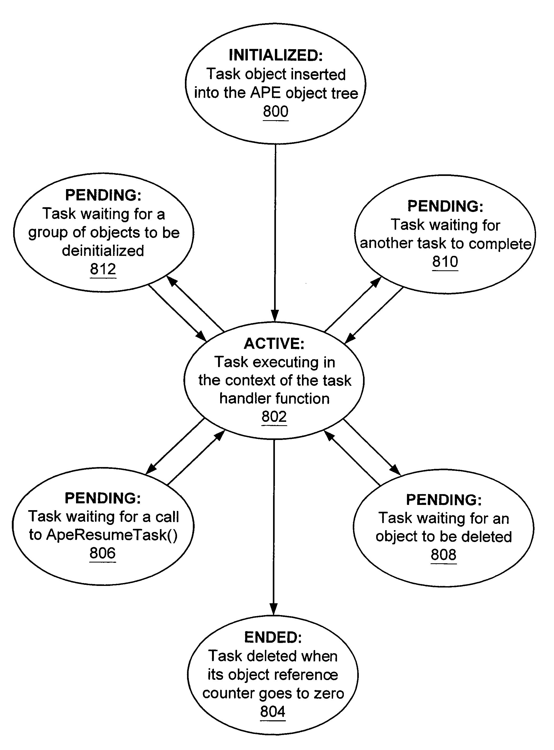
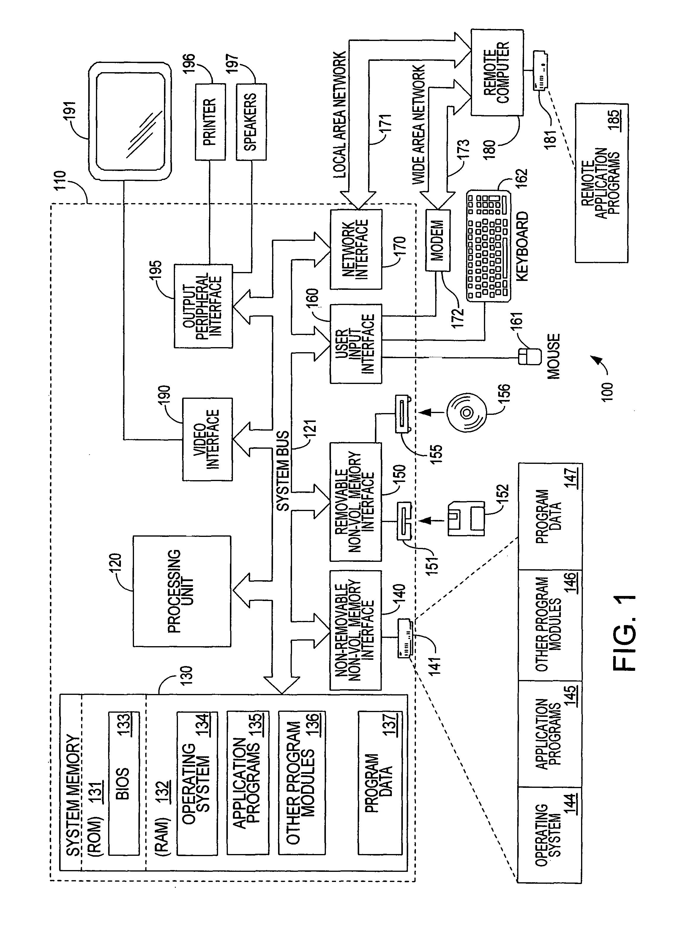
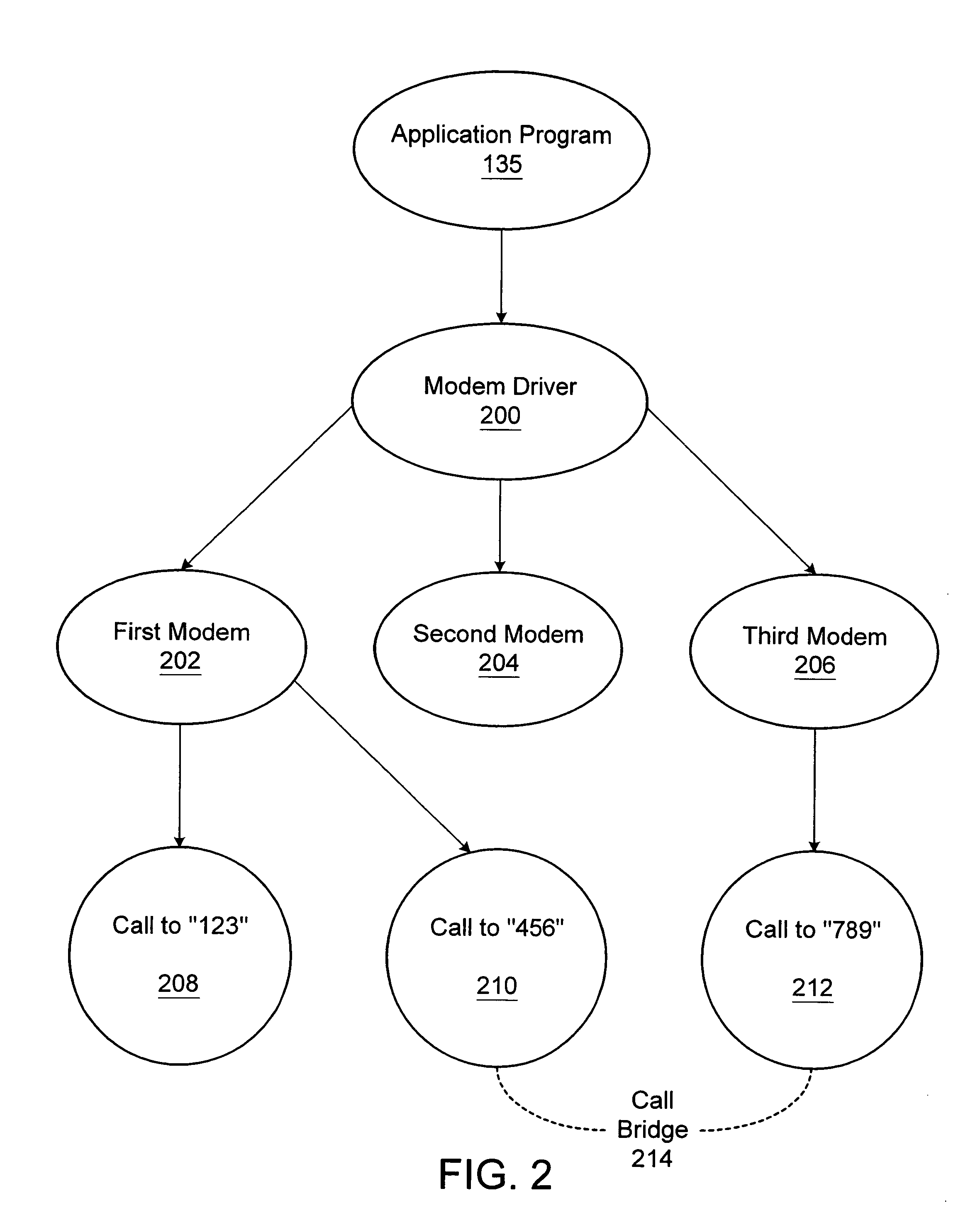
[0028]Turning to the drawings, wherein like reference numerals refer to like elements, the invention is illustrated as being implemented in a suitable computing environment. The following description is based on possible embodiments of the invention and should not be taken as limiting the invention in any way. The first section presents an exemplary hardware and operating environment in which the present invention may be practiced. Section II presents synchronous and asynchronous processing and highlights the differences between them. Section III describes how Input / Output Request Packets can be used to capture some of the structure of an asynchronous process. Sections IV through VII describe the Asynchronous Processing Environment (APE), an implementation of the present invention, showing how it captures the structure of an asynchronous process, counts object references, allows a group of objects to be treated as a group, and controls software locks. Debug associations are describe...


PUM


Abstract

The invention builds a structure of software objects that captures the historically contingent development of an asynchronous program. The invention builds software objects that represent the resources and subtasks that make up the asynchronous program. The objects are connected into a hierarchy whose structure explicates interactions among the resources and subtasks. When a fault is detected, the structure tells the debugger everything the program was doing at the time of the fault and lays open the developmental history of the program that led to the fault. The debugger uses this information to trace the detected fault back through code and time to its origin. When a new feature is added, the structure tells maintenance personnel how the new feature affects existing functions. Within the structure, the invention provides mechanisms for handling reference counters and software locks. Groups of resources can be handled together, the structure taking care of coordination.

Description

[0001]This application is a continuation of prior application Ser. No. 09 / 718,567, filed Nov. 22, 2000, entitled METHODS AND SYSTEMS FOR STRUCTURING ASYNCHRONOUS PROCESSES, which application is incorporated herein by reference.TECHNICAL FIELD[0002]The present invention relates generally to computer programming, and, more particularly, to structures and debugging aids for asynchronous processes.BACKGROUND OF THE INVENTION[0003]Software programs that handle complex tasks often reflect that complexity in their internal structures and in their interactions with other programs and events in their environment. Subtle errors may arise from mismatches between one part of the program and other parts of the same program, or between the program and the other programs in the environment. Mismatches include unexpected events, unplanned for sequences of events, data values outside the range of normalcy, updated behavior of one program not matched by updates in its peers, etc.[0004]Software develo...

Claims


Application Information

Patent Timeline
Patent Type & Authority Patents(United States)
IPC IPC(8): G06F9/46G06F9/44
CPCG06F11/3636G06F9/4411
Inventor JOY, JOSEPH M.DUBE, ADITYA
Owner MICROSOFT TECH LICENSING LLC
Learn More