
Interactive controller device

a controller and interface technology, applied in the direction of acceleration measurement using interia force, data acquisition and logging, instruments, etc., can solve the problem of not being able to uniquely determine

Inactive Publication Date: 2011-10-04
P&I
View PDF33 Cites 42 Cited by
  • Summary
  • Abstract
  • Description
  • Claims
  • Application Information

AI Technical Summary

Problems solved by technology

A difficulty is that, given only B and Bnew, one is unable to uniquely determine T, since there are infinitely many matrices, A, that will satisfy

Method used


Image

  • Interactive controller device
  • Interactive controller device
  • Interactive controller device

Examples


Embodiment Construction

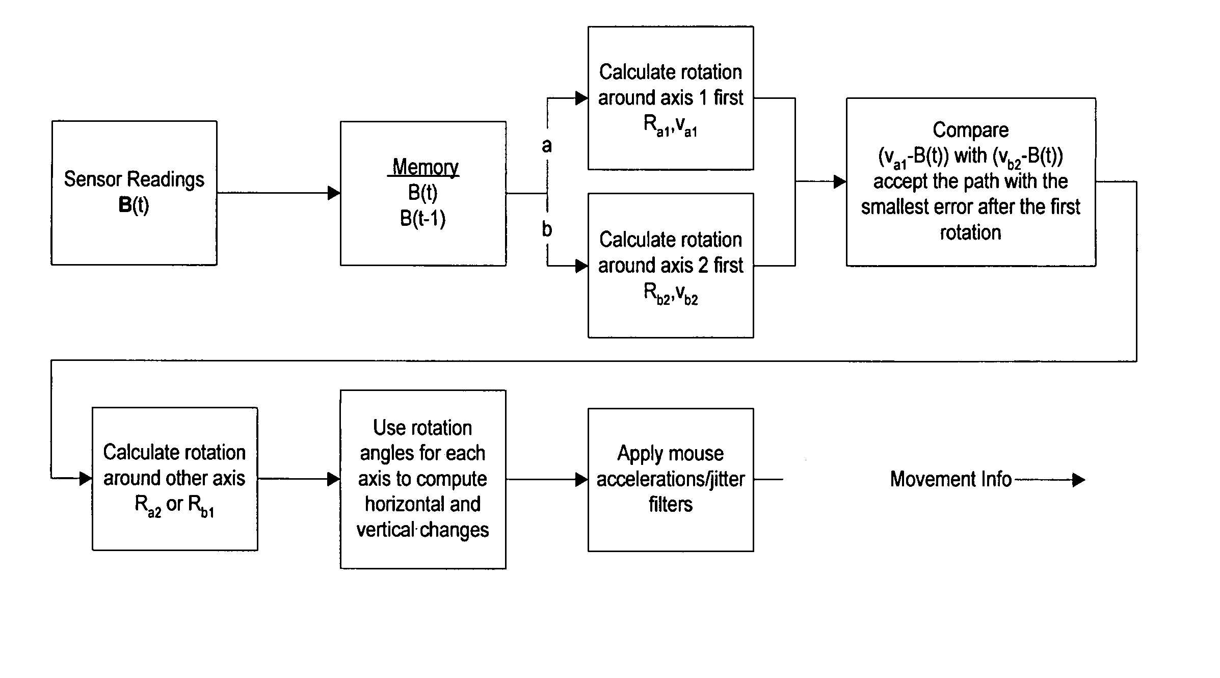
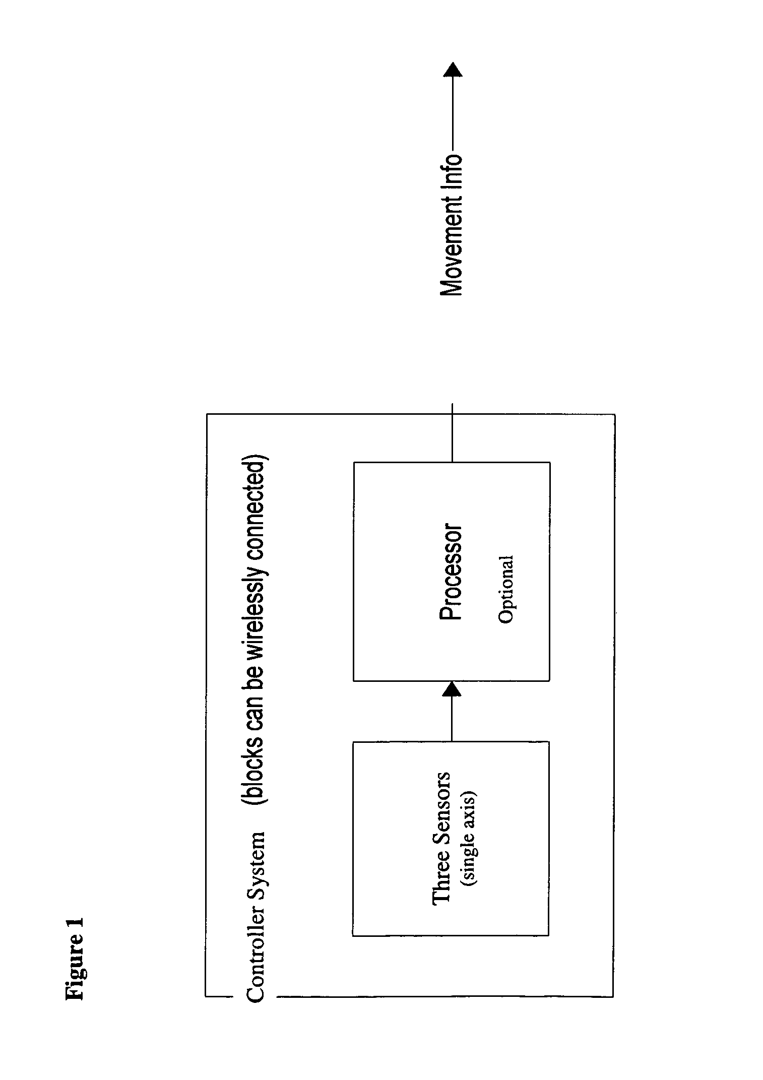
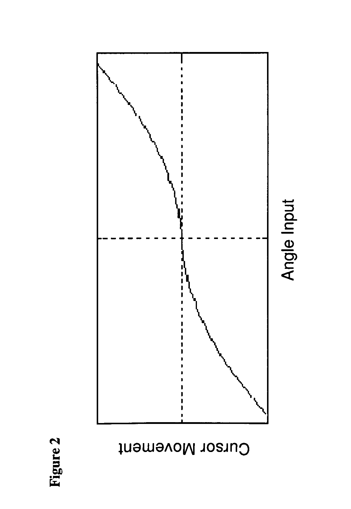
[0041]The instant invention discloses a method and system for an interactive controller device comprising at least a two axis magnetic field sensor; optionally other sensors may be added based on application. A time sequence of measurements in at least two linearly independent directions is used to extract the angles of rotation around one or more distinct axes; optionally a time sequence of measurements is also used to calculate the rate of change of angles of rotation and calculate accelerations and other variables of interest. Although it is not possible to uniquely determine the transformation, T, of a device orientation from a sequence of single vector measurements alone, one can approximately determine T as a combination of rotations about specified axes. Rotation angles for each time step may be used to calculate changes in a controller or pointer position on a display device. Rotation angles and rate of change may be used to measure the swing of a golf club, tennis racket or...


PUM


Abstract

A method and system for an interactive controller device comprising a two axis sensor in combination with one or more other sensors for hand-held devices operated in mid-air. A time sequence of measurements in three linearly independent directions is used to extract the angles of rotation around one or more distinct axes. A method is disclosed to approximately determine a transformation matrix, T, of a device orientation from a sequence of single vector measurements as a combination of rotations about specified axes. Calculated rotation angles can then be used to calculate changes in a controller or pointer position and a rate change thereof.

Description

PRIORITY[0001]This application claims priority from Provisional Application 60 / 956,907 filed on Aug. 20, 2007.CROSS-REFERENCE TO RELATED APPLICATIONS[0002]The present invention is related to U.S. Pat. No. 4,851,775, U.S. Pat. No. 5,239,264, U.S. Pat. No. 5,381,603, U.S. Pat. No. 6,243,660, U.S. Pat. No. 6,549,145, pending U.S. application Ser. Nos. 11 / 502,593, 12 / 017,161, and 11 / 856,973, and pending application Ser. No. 12 / 251,338; titled, “Spherical Calibration and Reference Alignment Algorithms”; filed on Oct. 14, 2008 wherein additional explanatory information is presented. Disclosure from these patents and applications is included herein in their entirety by reference.BACKGROUND OF THE INVENTION[0003]1. Field of the Invention[0004]The invention relates generally to user interface controllers and pointing devices, and particularly to a method and an apparatus to sense changes in a vector field (magnetic, acceleration, or other) to determine or estimate rotations about multiple ax...

Claims


Application Information

Patent Timeline
Patent Type & Authority Patents(United States)
IPC IPC(8): G06F17/16G06F17/40
CPCG01C17/02G01C25/005
Inventor BRYANT, TYLER MTAYLOR, ANDREW T.FIGARO, DAVY J.
Owner P&I
Learn More