
Current return network

a current return network and current return technology, applied in the installation of lighting conductors, electric devices, transportation and packaging, etc., can solve the problems of not being able to meet all of these functions, not providing the redundancy required for wiring, and increasing the cost and weight of metal structures and metal panels in moving apparatuses. to achieve the effect of minimizing resistance and voltage differential

Active Publication Date: 2011-10-04
THE BOEING CO
View PDF4 Cites 36 Cited by
  • Summary
  • Abstract
  • Description
  • Claims
  • Application Information

AI Technical Summary

Benefits of technology

The patent describes a composite moving apparatus that has conductive electrical pathways to carry current and provide grounding. The apparatus has longitudinal and lateral conductive electrical pathways that are connected to provide redundant electrical pathways. The technical effect of this invention is to provide a safer and reliable pathway for electrical current to flow through the composite moving apparatus.

Problems solved by technology

However, the use of metal structures and metal panels in moving apparatus increases cost and weight.
However, the wiring may not provide redundancies required to accommodate for faults in the system, and / or may not be adapted to handle all of these functions.

Method used


Image

  • Current return network
  • Current return network
  • Current return network

Examples


Embodiment Construction

[0011]The following detailed description is of the best currently contemplated modes of carrying out the disclosure. The description is not to be taken in a limiting sense, but is made merely for the purpose of illustrating the general principles of the disclosure, since the scope of the disclosure is best defined by the appended claims.

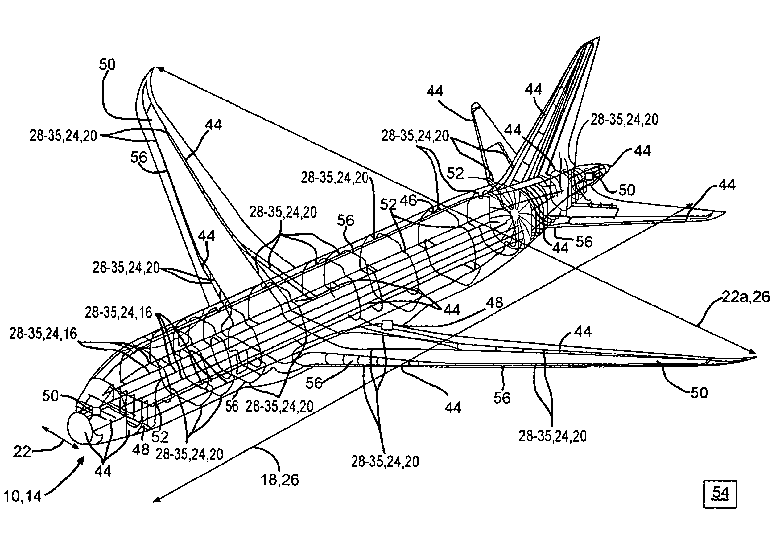
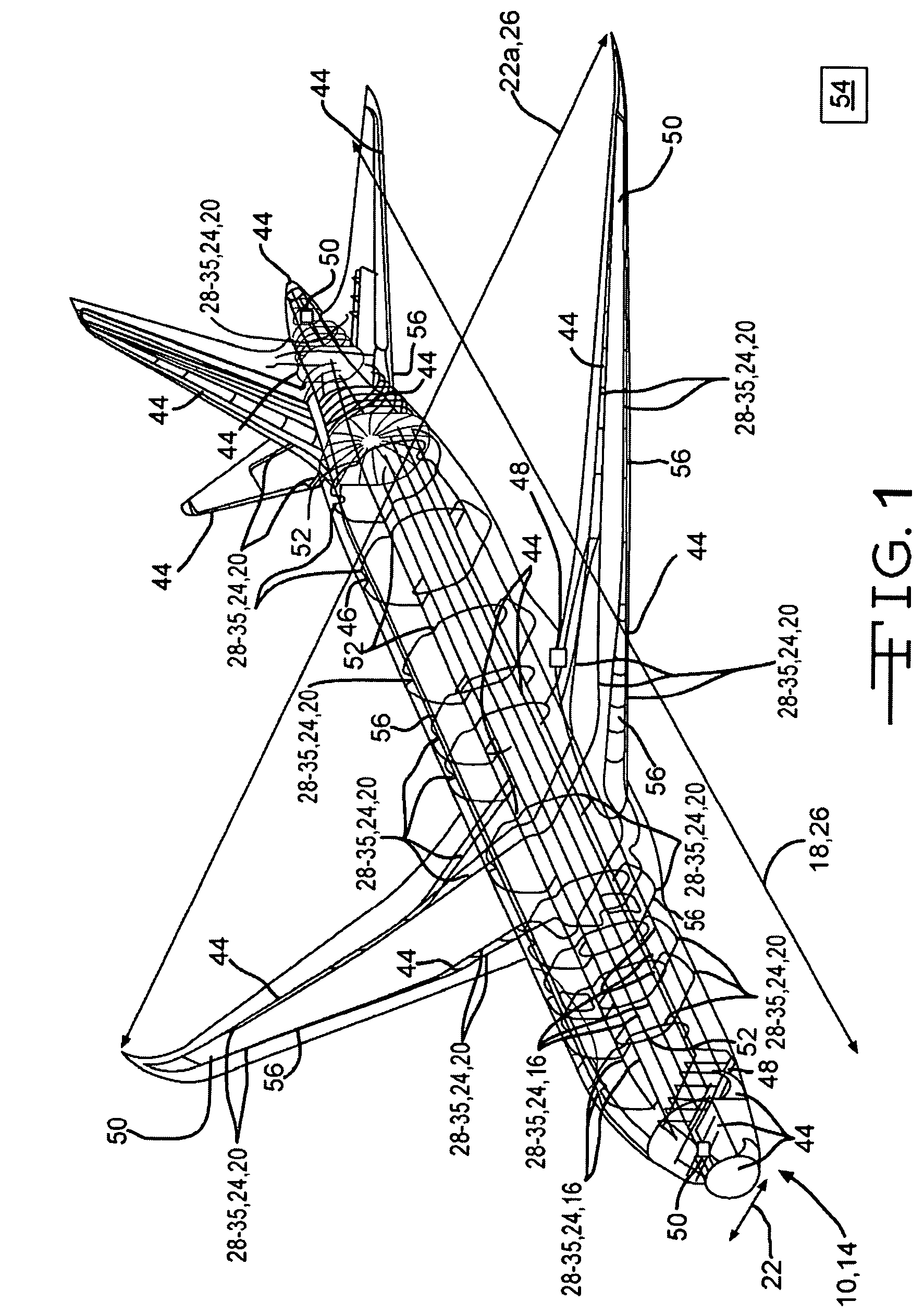
[0012]FIG. 1 shows a perspective view of one embodiment of a composite moving apparatus 10. The composite moving apparatus 10 of FIG. 1 is a composite aircraft. However, in other embodiments, the composite moving apparatus 10 may comprise a composite ship, a composite spacecraft, a composite satellite, a composite vehicle, a carbon fiber moving apparatus, and / or another type of composite moving apparatus. The composite moving apparatus 10 may be made substantially of composites 14. A plurality of longitudinal conductive electrical pathways 16 may extend along a substantial length 18 of the composite moving apparatus 10, and a plurality of lateral con...


PUM


Abstract

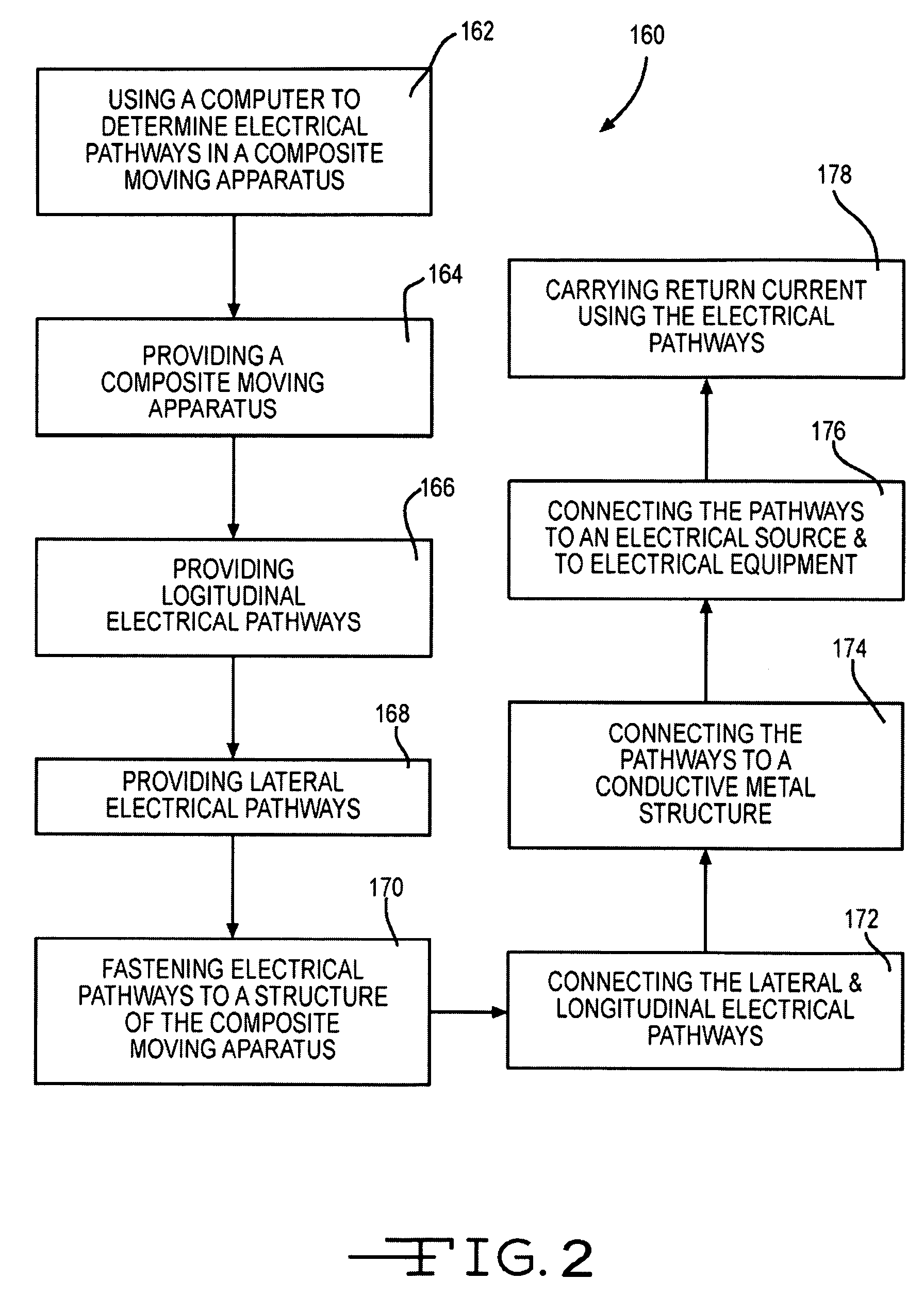
A composite moving apparatus made substantially of composites may include a plurality of longitudinal conductive electrical pathways extending along a substantial length of the composite moving apparatus, and a plurality of lateral conductive electrical pathways extending along a substantial lateral width of the composite moving apparatus. The longitudinal and lateral conductive electrical pathways may be connected in order to provide redundant electrical pathways extending along a substantial portion of the composite moving apparatus. The redundant electrical pathways may carry return current, carry fault current, provide grounding, carry lightning current, provide electromagnetic shielding, minimize resistance and voltage differential, and / or provide a bleed path for electrostatic charge.

Description

FIELD OF THE DISCLOSURE[0001]The disclosure relates to conductive electrical pathways disposed in apparatus.BACKGROUND OF THE DISCLOSURE[0002]Many moving apparatus, such as aircraft, spacecraft, ships, satellites, vehicles, and other types of moving apparatus, are made of metal and utilize their metal panels and structures in order to provide conductive electrical pathways for the return of normal direct current and alternating operating current, carrying fault currents, providing grounding, earning lightning current, providing electromagnetic shielding, minimizing resistance and voltage differentials, and / or for providing bleed paths for electrostatic charge. However, the use of metal structures and metal panels in moving apparatus increases cost and weight. Alternatively, discrete wiring has been used to serve one or more of these functions. However, the wiring may not provide redundancies required to accommodate for faults in the system, and / or may not be adapted to handle all of...

Claims


Application Information

Patent Timeline
Patent Type & Authority Patents(United States)
IPC IPC(8): H05F3/00
CPCH02G13/00
Inventor BRADEN, STEPHEN M.DOHERTY, MICHAEL J.SCOTT, STEPHEN M.
Owner THE BOEING CO
Learn More