
Power circuit used for an amplifier

a power circuit and amplifier technology, applied in the direction of rf amplifiers, high-frequency amplifiers, gain control, etc., can solve the problems of limited ac components, limited self-oscillating frequency, limited dc/dc converter switching loss, etc., to prevent the effect of reducing efficiency and increasing the switching loss of dc/dc converter

Inactive Publication Date: 2011-10-04
KOKUSA ELECTRIC CO LTD
View PDF4 Cites 21 Cited by
  • Summary
  • Abstract
  • Description
  • Claims
  • Application Information

AI Technical Summary

Benefits of technology

This configuration allows the DC / DC converter to operate at high efficiency with respect to the DC component, maintaining overall power circuit efficiency even under wideband conditions by restricting the switching interval and reducing energy loss.

Problems solved by technology

The distortion compensation function includes a feed-forward compensation function, a pre-distortion compensation function or the like, but there is a limitation in the lowering of power consumption by only using the distortion compensation.
However, if the self-oscillating frequency is set to be high, since switching loss is increased or it exceeds a limit value of the switch device 32, the self-oscillating frequency is limited.
However, since a band of the communication system such as the WiMAX or the LTE is wide and a band of the envelope signal becomes wider, the AC component is limited.
However, in the wideband communication system such as the WiMAX or the LTE, since the envelope exists in a wide range, if the switching frequency of the DC / DC converter 15 is raised, switching loss is increased, so that the efficiency of the power circuit is reduced.
Consequently, the efficiency of the power circuit is reduced.

Method used


Image

  • Power circuit used for an amplifier
  • Power circuit used for an amplifier
  • Power circuit used for an amplifier

Examples


embodiment 1

[0096]Hereinafter, Embodiment 1 of the invention will be described with reference to the drawings.

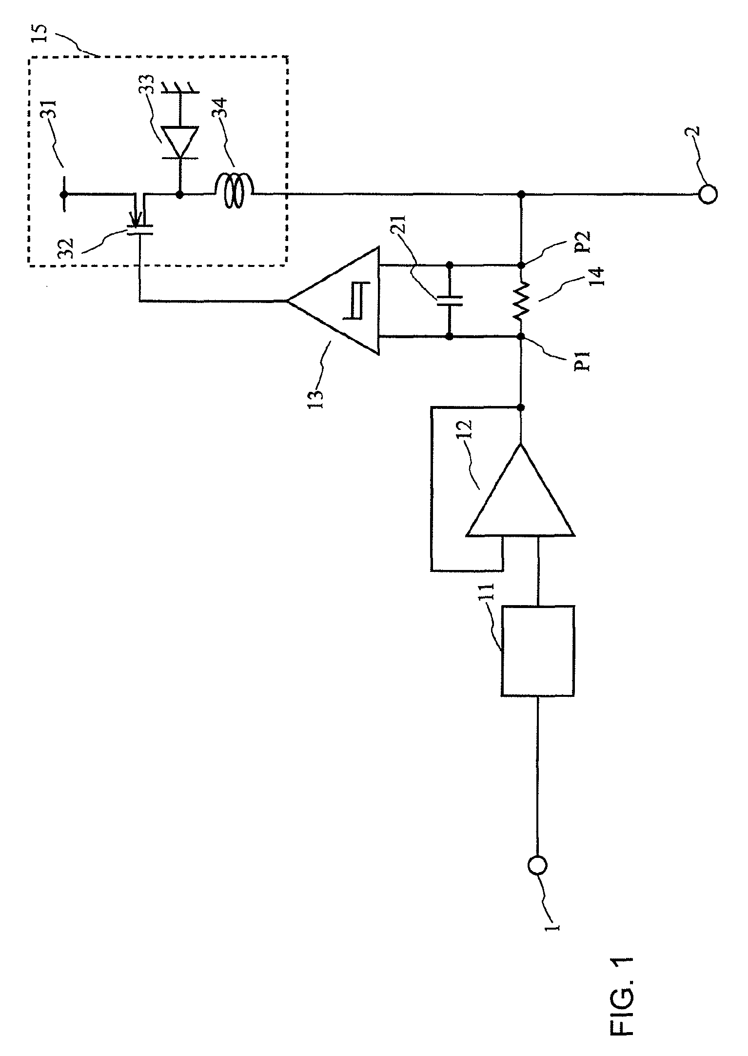
[0097]FIG. 1 is a circuit diagram showing an example of an envelope amplifier (power circuit) according to one embodiment of the invention. For the purpose of convenience, the same reference numerals are used to designate the same elements as those shown in FIG. 6, and it does not unnecessarily limit the invention.

[0098]The envelope amplifier of the embodiment includes a waveform shaper 11, an OP amp 12, a hysteresis comparator 13, a current detector 14, a capacitor 21 and a DC / DC converter 15, which are provided between an input terminal 1 and an output terminal 2.

[0099]The DC / DC converter 15 includes a supply voltage 31, a switch device 32, a diode 33 and an inductance 34.

[0100]Further, FIG. 1 shows nodes P1 and P2.

[0101]In detail, an input terminal of the waveform shaper 11 is connected to the input terminal 1, an output terminal of the waveform shaper 11 is connected to one input te...

example 1

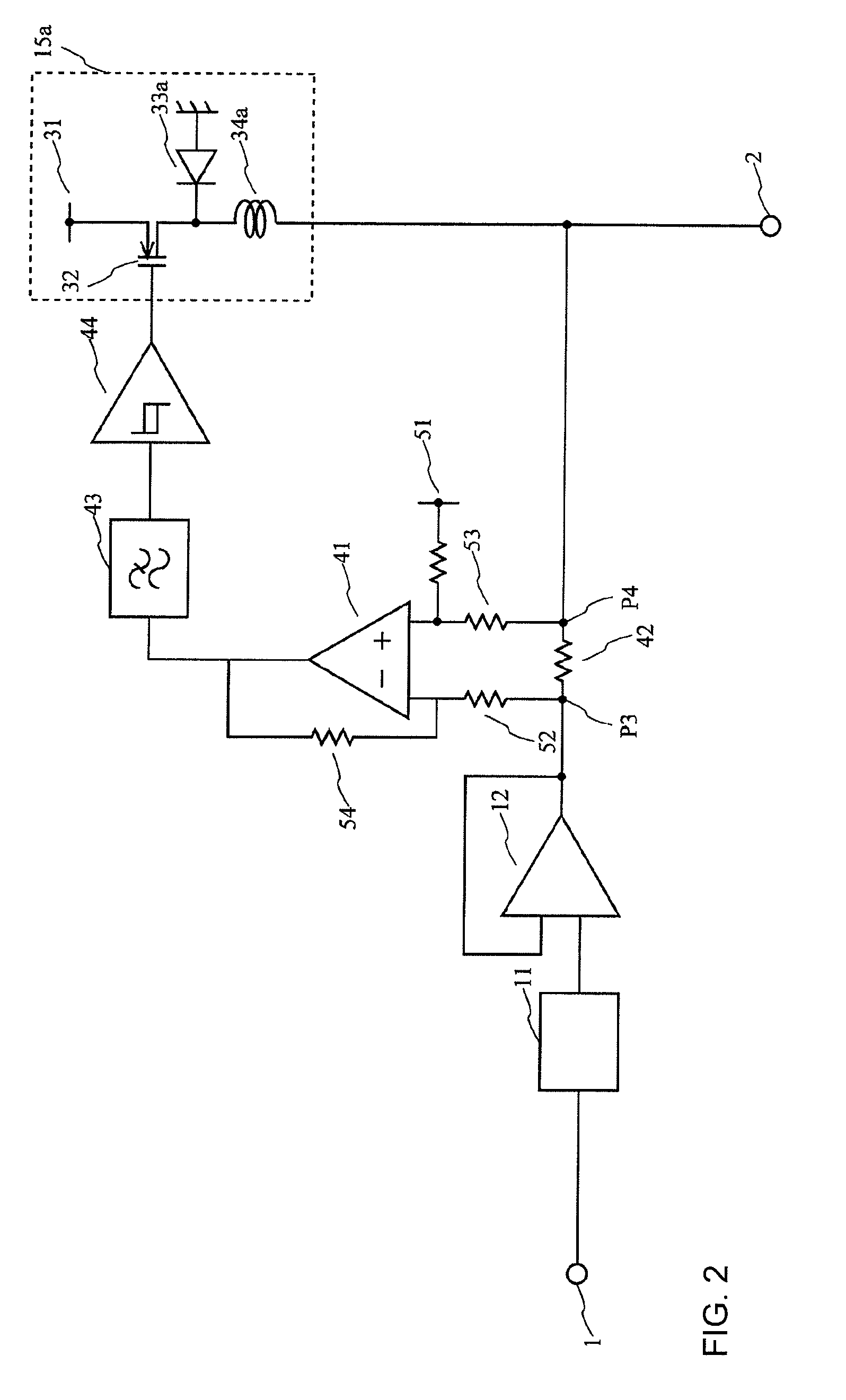
[0148]The low pass filters (the capacitor 21, the low pass filter 43 and the capacitor 71 in the embodiment) are each inserted to input to the hysteresis comparators 13, 44 and 64 constituting the linear assist class BD amplifier, so that the operation frequency of the class D amplifier is suppressed.

[0149]In detail, in the embodiment, the linear assist class BD amplifier is used as a power source in which power used for the linear amplifier is changed based on the envelope information, the low pass filter is inserted after the current detection of the linear assist class BD amplifier so that information of a high frequency component is removed, and the operation frequency of the class D amplifier (the DC / DC converter) is restricted, so that the efficient power circuit can be realized (e.g., the configurations of FIGS. 1 to 3).

example 2

[0150]The linear assist class BD amplifier is applied to the linear amplifier (the OP amp 12 in the embodiment) constituting the linear assist class BD amplifier.

[0151]In detail, in the embodiment, the linear assist class BD amplifier is used as a power source in which power used for the linear amplifier is changed based on the envelope information, and the linear assist class BD amplifier is employed with respect to the power of the linear assist class BD amplifier (e.g., the configuration of FIG. 3).


PUM


Abstract

A power circuit used for an amplifier, which includes an amplifier provided with a linear amplifier serving as a voltage source, a DC / DC converter serving as a current source, a hysteresis comparator controlling the DC / DC converter, and a current detector detecting output current from the linear amplifier to output the detected output current to the hysteresis comparator; and a switching restricting device for restricting a switching interval in the DC / DC converter such that the switching interval is not equal to or less than a constant time or is not shorter than the constant time.

Description

BACKGROUND OF THE INVENTION[0001]1. Technical Field of the Invention[0002]The present invention relates to a power circuit, for example, capable of preventing efficiency from being reduced by an increase in switching loss of a DC / DC converter when a wideband envelope signal is received.[0003]2. Description of the Related Art[0004]According to the related art, when a radio frequency signal such as a CDMA (Code Division Multiple Access) signal or a multi-carrier signal is power-amplified, a distortion compensation function is added to a common amplifier and an operation range of the common amplifier is expanded up to the vicinity of a saturation region, so that low power consumption is achieved. The distortion compensation function includes a feed-forward compensation function, a pre-distortion compensation function or the like, but there is a limitation in the lowering of power consumption by only using the distortion compensation. In this regard, in recent years, a method of achievi...

Claims


Application Information

Patent Timeline
Patent Type & Authority Patents(United States)
IPC IPC(8): H03G3/00
CPCH03F1/0227H03F3/19H03F2200/451H03F2200/462
Inventor OKUBO, YOICHINAKAMURA, MANABUDOSAKA, JUNYATAKEDA, YASUHIROITO, TAIZOHONGO, NAOKIYAMAWAKI, TAIZOKAWAMOTO, TAKASHIMAEKI, AKIRA
Owner KOKUSA ELECTRIC CO LTD
Learn More