
Method of transmitting data in a wireless communication system

a wireless communication system and wireless communication technology, applied in the field of wireless communication systems, can solve the problems of system overhead and waste of channel resources in the overall system, and achieve the effect of efficient use of radio resources

Inactive Publication Date: 2011-09-27
LG ELECTRONICS INC
View PDF111 Cites 46 Cited by
  • Summary
  • Abstract
  • Description
  • Claims
  • Application Information

AI Technical Summary

Benefits of technology

[0013]Accordingly, the present invention is directed to a method of transmitting data in a wireless communication system, which substantially obviates one or more problems due to limitations and disadvantages of the related art. An object of the present invention is to provide a method of transmitting data in a wireless communication system, in which radio resources can be used efficiently.

Problems solved by technology

For example, considering that one length field is allocated per MAC SDU having a size of 100 bits to 200 bits, voice packets occupy a considerable part in one MAC PDU, thereby causing channel resources to be wasted in the overall system.
In this case, a problem occurs in that overhead may be caused in the system.

Method used


Image

  • Method of transmitting data in a wireless communication system
  • Method of transmitting data in a wireless communication system
  • Method of transmitting data in a wireless communication system

Examples


Embodiment Construction

[0023]Hereinafter, structures, operations, and other features of the present invention will be understood readily by the preferred embodiments of the present invention, examples of which are illustrated in the accompanying drawings.

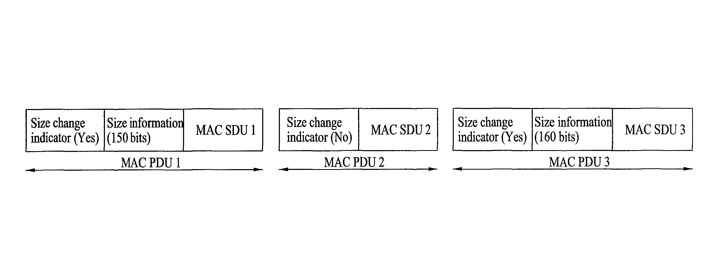
[0024]FIG. 4 illustrates a structure of data blocks according to one embodiment of the present invention.

[0025]Referring to FIG. 4, MAC PDU 1 includes a size change indicator, size information, and MAC SDU 1. The size change indicator indicates whether a size (or length) of the MAC SDU 1 is identical with that of a corresponding MAC SDU previously generated in MAC layer of a transmitting side and transmitted to a receiving side, wherein the MAC SDU is included in MAC PDU. The size information means information indicating the size of the MAC SDU 1 if the size change indicator indicates that the size of the MAC SDU 1 has been changed in comparison with that of the previous MAC SDU. The MAC SDU 1 is an upper layer data block transferred from an RLC layer, wh...


PUM


Abstract

A method of configuring a lower layer data block in a protocol layer of a transmitting side of a wireless communication system comprises receiving upper layer data from an upper layer, and configuring a second lower layer data block to include a first upper layer data block comprising at least part of the upper layer data, and a size change indictor indicating whether a size of the first upper layer data block is identical with a size of a second upper layer data block included in a first lower layer data block.

Description

[0001]This application claims priority to International Application No. PCT / KR2008 / 002457 filed on Apr. 30, 2008, which claims priority to Provisional Application Nos. 60 / 915,042 filed on Apr. 30, 2007, 60 / 915,417 filed on May 1, 2007 and Korean Patent Application No. 10-2008-0040508 filed on Apr. 30, 2008, all of which are incorporated by reference for all purposes as if fully set forth herein.TECHNICAL FIELD[0002]The present invention relates to a wireless communication system, and more particularly, to a method of transmitting data in a wireless communication system.BACKGROUND ART[0003]FIG. 1 illustrates a network structure of an E-UMTS (Evolved-Universal Mobile Telecommunications System). An E-UMTS is a system evolving from the conventional WCDMA (wideband code division multiple access) UMTS and its basic standardization is currently handled by the 3GPP (3rd Generation Partnership Project). The E-UMTS can also be called an LTE (Long Term Evolution) system.[0004]Referring to FIG....

Claims


Application Information

Patent Timeline
Patent Type & Authority Patents(United States)
IPC IPC(8): H04J3/16
CPCH04L12/1886H04W28/06H04L69/04H04L69/22H04L69/324H04L12/189H04W80/02
Inventor CHUN, SUNG DUCKLEE, YOUNG DAEPARK, SUNG JUNYI, SEUNG JUNE
Owner LG ELECTRONICS INC
Learn More