Eureka AIR delivers breakthrough ideas for toughest innovation challenges, trusted by R&D personnel around the world.

Artificial meniscus and process of making thereof

a technology of meniscus and process, applied in the field of artificial meniscus, can solve the problems of not having materials capable of withstanding such severe environment, requiring a great deal of time and cost to reach regeneration, etc., and achieves the effects of preventing osteoarthritis, and reducing the risk of injury

Inactive Publication Date: 2011-09-27
HOKKAIDO UNIVERSITY
View PDF31 Cites 11 Cited by
  • Summary
  • Abstract
  • Description
  • Claims
  • Application Information

AI Technical Summary

Benefits of technology

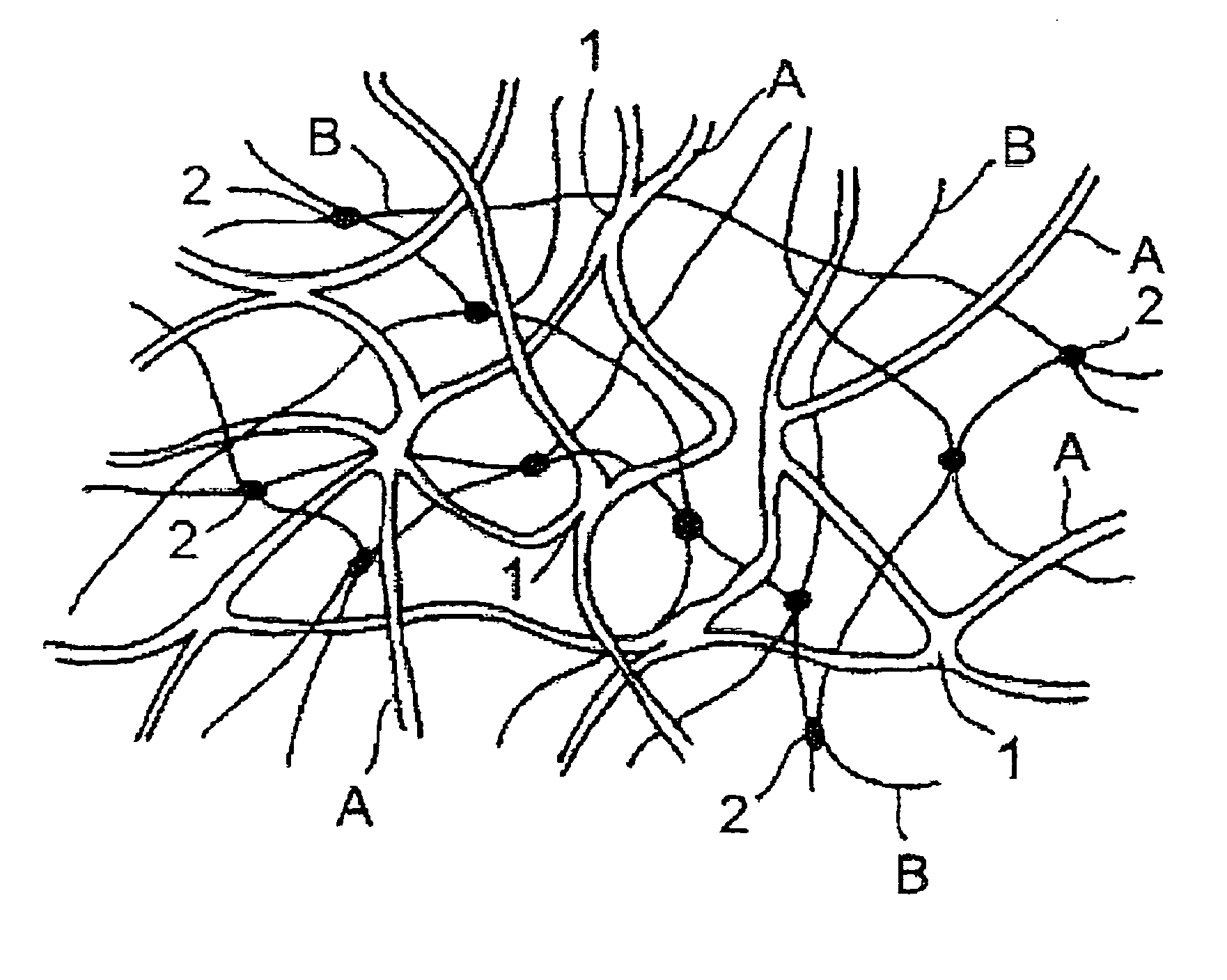
[0026]The artificial meniscus according to the present invention, when applied for an extended period of time in an organism, can maintain moderate mechanical properties for an extended period of time and will not induce any osteoarthritis. Therefore, the artificial meniscus according to the present invention is useful as prostheses for lost menisci and can prevent osteoarthritis induced by an extended period of having the meniscus lost and, when osteoarthritis have already developed, is expected to alleviate or cure the symptoms. While it is unclear why the artificial meniscus according to the present invention shows the effects comparable to the natural meniscus for an extended period of time, the artificial meniscus according to the present invention is estimated to possess one or any combination or all of the functionalities required for the meniscus: 1) shock absorption of the articular cartilages, 2) contribution to stabilization of the joints, 3) nutrient supply to the articular cartilages, 4) prosthesis of unmatched joints, and 5) assistance of lubrication.

Problems solved by technology

However, for meniscal implantation, it is highly difficult to obtain menisci in our country and, also for regeneration medicine, it has not yet been put into practical use as of this moment and is expected to require a great deal of time and cost to reach regeneration.
As described above, however, since between the joints is where the severest mechanical environment is found in an organism, materials capable of withstanding such severe environment do not exist at the moment.

Method used


Image

  • Artificial meniscus and process of making thereof
  • Artificial meniscus and process of making thereof
  • Artificial meniscus and process of making thereof

Examples


example 1

Preparation of Single-Network Type Gel

[0108]From a silicon plate having an area of 100 mm×100 mm and a thickness of 2 mm, a frame having outer sides of 80 mm×80 mm and a width of 5 mm was cut out with a cutter and a groove of 3 mm was bored on a location on the frame. This silicon frame was interposed between two glass plates each having an area of 100 mm×100 mm and a thickness of 3 mm to assemble a polymerization reactor.

[0109]25 ml of an aqueous solution of 2 mol / L 2-acrylamido-2-methylpropane sulfonic acid (AMPS) as a monomer, 1 ml of an aqueous solution of 2 mol / l N,N′-methylenebisacrylamide (MBAA) as a crosslinker and 1 ml of an aqueous solution of 0.1 mol / L 2-oxoglutaric acid as an initiator were combined and conditioned with water to obtain 50 ml of an aqueous solution. This solution was deoxygenated using nitrogen gas. Subsequently, the deoxygenated solution was poured into an opening of the silicon plate placed on one of the glass plates of the polymerization reactor and th...

example 2

Preparation of Single-Network Type Gel

[0116]40 ml of an aqueous solution of 2 mol / L acrylic acid (AA) as a monomer, 4 ml of an aqueous solution of 0.2 mol / L N,N′-methylenebisacrylamide (MBAA) as a crosslinker and 1 ml of an aqueous solution of 0.1 mol / L 2-oxoglutaric acid as an initiator were combined and conditioned with water to obtain 80 ml of an aqueous solution. The solution was deoxygenated using a nitrogen gas. Subsequently, the deoxygenated solution was poured into an opening of a silicon plate placed on one of glass plates of a polymerization reactor similar to one in Example 1 and the other glass plate was superposed on the silicon plate to seal around the opening. Then, polymerization was carried out using a UV lamp having a wavelength of 365 nm (22 W, 0.34 A) to irradiate ultraviolet radiation at a normal temperature for six hours to prepare an AA gel having a degree of crosslinking of 1 mol %.

Preparation of Double-Network Type Gel

[0117]20 ml of an aqueous solution of 5 ...

example 3

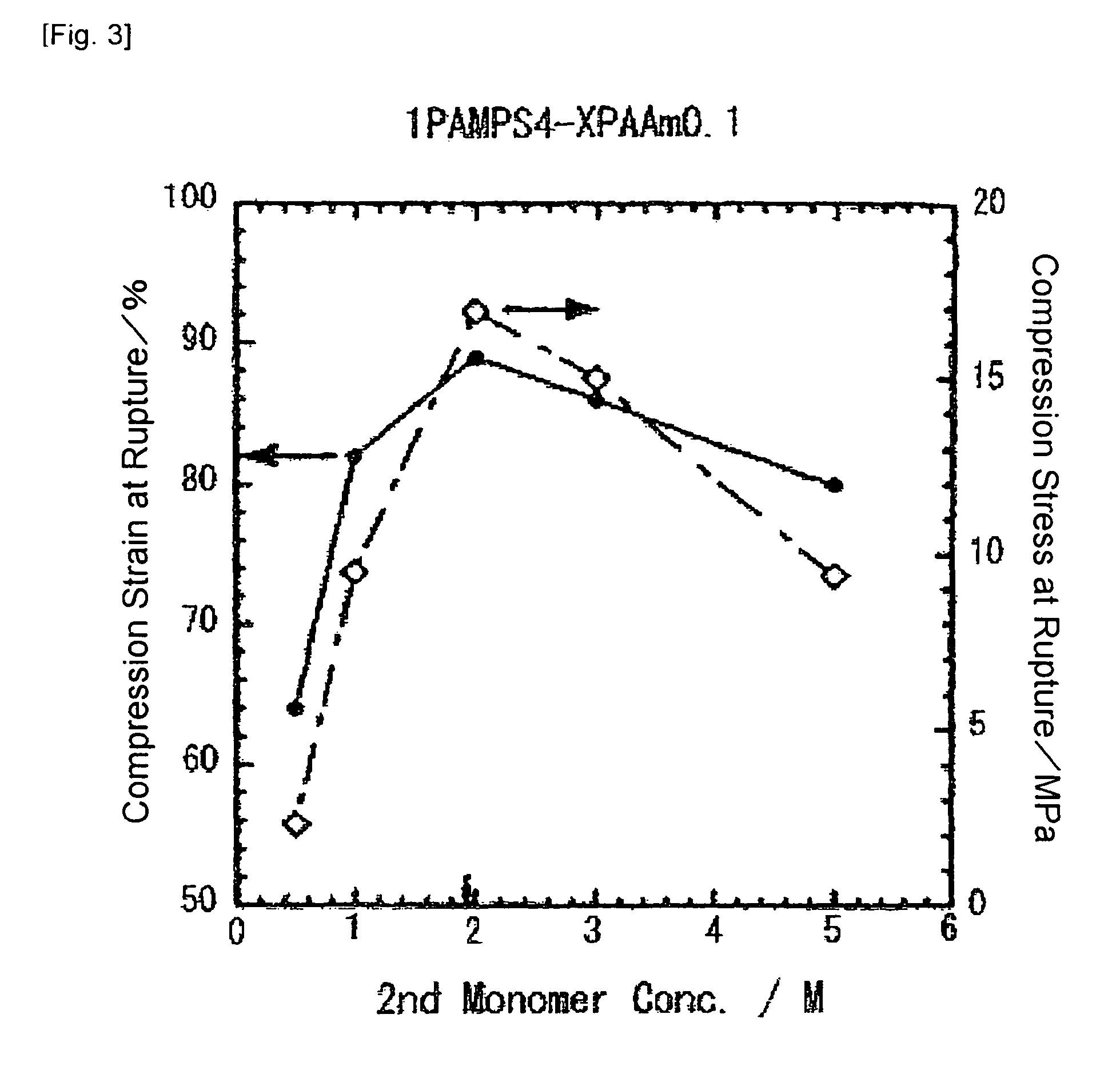
[0124]In a similar manner as in Example 1, but altering the ratio between the monomers composing the first and second network structures and also altering the degrees of crosslinking of the first and second network structures, mechanical strength was measured. Below, an abbreviated designation is used for each double-network type gel, consisting of first monomer concentration (M), monomer name and degree of crosslinking (mol %)-second monomer concentration (M), monomer name and degree of crosslinking (mol %) in the mentioned order. For example, a double-network type gel in which a first network structure is PAMPS having a monomer concentration of 1 M and a degree of crosslinking of 4 mol %, and a second network structure is PAAm having a monomer concentration of 1 M and a degree of crosslinking of 0.1 mol % is designated as 1PAMPS4-1PAAm0.1. It should be noted that the monomer concentrations here are those at the time of production and differ from the monomer amounts in the final ge...


PUM

PropertyMeasurementUnit
mol %aaaaaaaaaa
mol %aaaaaaaaaa
degree of crosslinkingaaaaaaaaaa

Abstract

An artificial meniscus, a base material of which is a hydrogel having a semi-interpenetrating network structure or an interpenetrating network structure (e.g., a linear polymer or a network structure composing the hydrogel is a polymer of an electrically charged unsaturated monomer and / or an electrically neutral unsaturated monomer or a crosslinked product thereof or / and a naturally occurring macromolecule or a crosslinked product thereof.), which can maintain moderate mechanical properties even in the case of application for an extended period of time between the joints where the severest mechanical environment is found in an organism, and which has no fear of causing osteoarthritis.

Description

[0001]This application is a U.S. National Phase Application under 35 USC 371 of International Application PCT / JP004 / 008599, filed Jun. 18, 2004, which is incorporated herein in its entirety by this reference.TECHNICAL FIELD[0002]The present invention relates to artificial menisci which, even if positioned for an extended period of time between the joints under the severest mechanical environment in an organism, can maintain moderate mechanical strength and have no risk of developing any osteoarthritis.BACKGROUND ART[0003]Knee joints are required to have functionalities under the severest mechanical environment rather than characteristics of the surface shape of the joints and the degree of freedom for joint motions. Important functions such as load transmission and shock absorption are assumed by a meniscus.[0004]The meniscus exists between the femur and the tibia to assume the action of dispersing the load applied from the femur for absorbing shocks and the role of providing stabil...

Claims


Application Information

Patent Timeline
Patent Type & Authority Patents(United States)
IPC IPC(8): A61F2/08A61F2/00
CPCA61L27/26A61L27/52C08L1/00C08L101/02C08L5/04A61L2430/06
Inventor OSADA, YOSHIHITOGONG, JIAN PINGYASUDA, KAZUNORI
Owner HOKKAIDO UNIVERSITY
Why Eureka
Eureka Blog
Learn More