Methods, systems and devices for performing gynecological procedures
a gynecological and system technology, applied in the field of gynecological procedures, can solve the problems of occlusion of the fallopian tube and the cost of procedures often large, and achieve the effect of reducing the risk of complications
- Summary
- Abstract
- Description
- Claims
- Application Information
AI Technical Summary
Benefits of technology
Problems solved by technology
Method used
Image
Examples
first embodiment
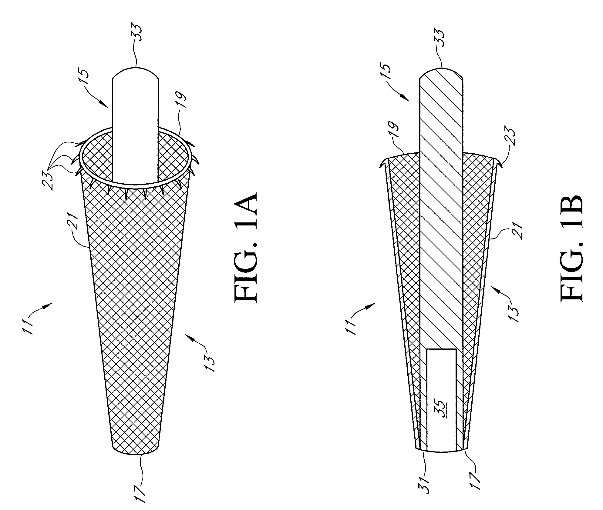
[0036]Referring now to FIGS. 1(a) and 1(b), there are shown perspective and longitudinal section views, respectively, of an occlusion device for a fallopian tube, the occlusion device being constructed according to the teachings of the present invention and being represented generally by reference numeral 11.
[0037]Device 11 may include an outer member 13 and an inner member 15. Outer member 13, which may be a self-expandable structure adapted to engage the inner wall of a fallopian tube, may comprise a hollow, frusto-conical structure shaped to include an open proximal end 17, an open distal end 19, and a side wall 21. Outer member 13 may be made of a resilient or shape-memory material, such as Nitinol (nickel-titanium alloy), so that distal end 19 may be biased radially outwardly. In addition, outer member 13 may be fabricated so that side wall 21 has a mesh structure or other porous structure to permit the ingrowth of tissue therethrough. A plurality of anchoring tines 23 may be p...
second embodiment
[0041]Referring now to FIGS. 3(a) and 3(b), there are shown exploded side and longitudinal section views, respectively, of an occlusion device for a fallopian tube, the occlusion device being constructed according to the teachings of the present invention and being represented generally by reference numeral 101.
[0042]Device 101 may comprise a first portion 103, a second portion 105, and a third portion 107. First portion 103 may comprise a tube 109. Tube 109, which may be appropriately dimensioned to be inserted coaxially into a fallopian tube, may be shaped to include an open proximal end 111, an open distal end 113 and a side wall 115. Side wall 115, which may be cylindrical in shape, may possess a mesh or other porous structure to permit the ingrowth of tissue therethrough. (For clarity and simplicity, the porosity of side wall 115 is not shown in FIG. 3(b).) A first end 116 of a pawl 117 may be pivotally mounted on a pivot pin 119 on the inner surface of side wall 115 proximate ...
seventh embodiment
[0048]Referring now to FIG. 9, there is shown a longitudinal section view of a tubal occlusion device constructed according to the teachings of the present invention, the tubal occlusion device being represented generally by reference numeral 301.
[0049]Device 301, which is similar in certain respects to the device disclosed in U.S. Pat. No. 4,735,194, which is incorporated herein by reference, may include a flexible scope 310 equipped with a suction channel 311 and a fiberoptics illumination channel 312, both exiting at a terminal 313 which may be connected to a control box (not shown) for supplying suction and illumination. In addition, scope 310 may be equipped with a balloon channel 305 for slidably receiving an inflation catheter 307 for a balloon. An eyepiece 314 may provide means for viewing the procedure either directly or by video camera and subsequent projection onto a video monitor. A trip wire 315, located in a channel 316, may be equipped with a weighted handle 317 and m...
PUM
 Abstract
Description
Claims
Application Information
 - R&D
- Intellectual Property
- Life Sciences
- Materials
- Tech Scout
- Unparalleled Data Quality
- Higher Quality Content
- 60% Fewer Hallucinations
Browse by: Latest US Patents, China's latest patents, Technical Efficacy Thesaurus, Application Domain, Technology Topic, Popular Technical Reports.
© 2025 PatSnap. All rights reserved.Legal|Privacy policy|Modern Slavery Act Transparency Statement|Sitemap|About US| Contact US: help@patsnap.com


