
Method and apparatus for separating and dewatering slurries

a technology of slurries and methods, applied in the direction of separation processes, sedimentation settling tanks, filtration separation, etc., can solve the problems of unenforceable clean water act of 2002, ineffective prior art dewatering systems, and frightening destruction rate of ground water, and achieve economic effect of manufactur

Inactive Publication Date: 2011-09-27
TAPP FLOYD G
View PDF9 Cites 8 Cited by
  • Summary
  • Abstract
  • Description
  • Claims
  • Application Information

AI Technical Summary

Benefits of technology

"The present invention is a solid-liquid separating and dewatering machine designed for dairy and swine farmers. The machine helps reduce environmental issues by separating and dewatering manure and other waste. It achieves this by maintaining the porosity of particles, allowing air to displace moisture from between them. The machine can be adjusted for different slurries and can produce valuable products like fertilizer, compost, and biogas. It can also be used to dewater coal fines, which can be combined with fiber from animal feeding operations to produce energy. The invention is simple, dependable, and economical to manufacture."

Problems solved by technology

Our ground water is being destroyed at a frightening rate by the concentrated animal feed operations (CAFO's).
The lack of efficient dairy and swine manure management equipment has made The Clean Water Act of 2002 unenforceable.
Prior art dewatering systems are not effective because they attempt to press the moisture from the particles and the end result is a compacted mass of wet fiber with little porosity.
Without the ability to move the filtrate through the cake the throughput is limited.
These things can't be done cost-effectively without an efficient solid-liquid separation (SLS) concept.
They all have one or more of the following problems: expensive, unreliable, low throughput, reduced porosity, filter cake blinding, and they fail to meet acceptable moisture levels.

Method used


Image

  • Method and apparatus for separating and dewatering slurries
  • Method and apparatus for separating and dewatering slurries
  • Method and apparatus for separating and dewatering slurries

Examples


Embodiment Construction

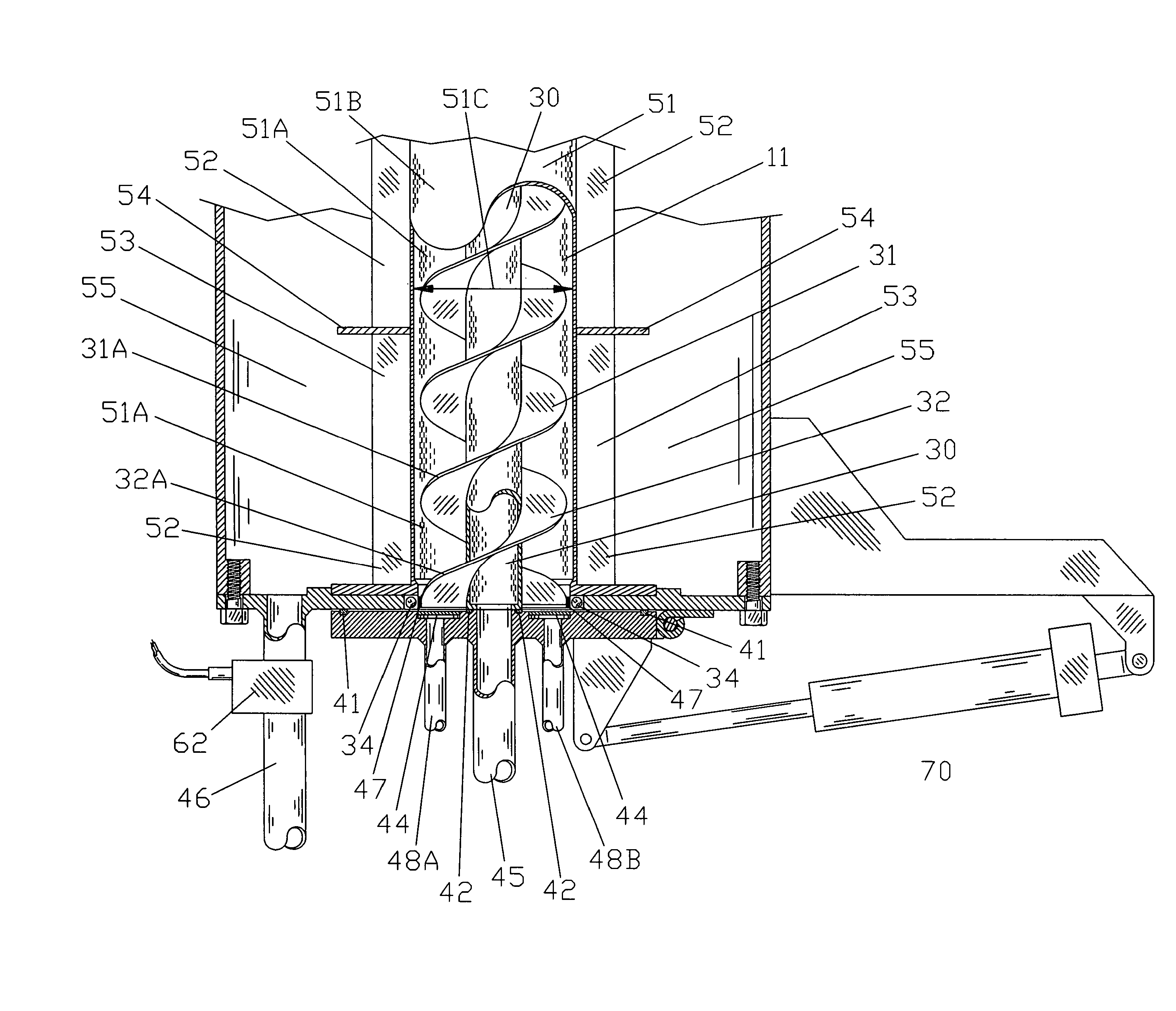
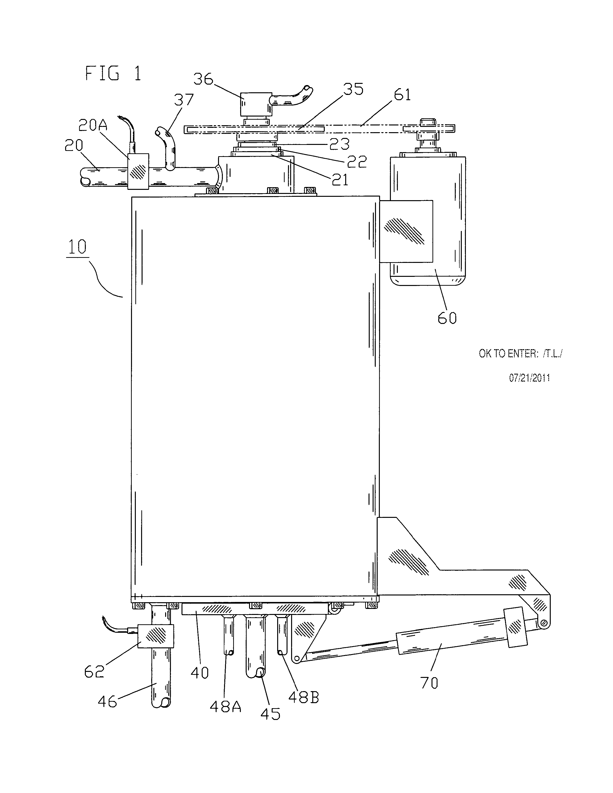
[0027]In accordance with the present invention, a vertical fiber and solids separation and dewatering system is disclosed. The vertical dewatering apparatus system uses compressed air to displace the moisture from between the particles with minimum compressing of the particles. The compressed air is supplied through an inner screen that is preferably a perforated shaft used to drive flightings to remove the dried cakes. In the broadest context, the apparatus of the present invention consists of components configured and correlated with respect to each other so as to attain the desired objective.

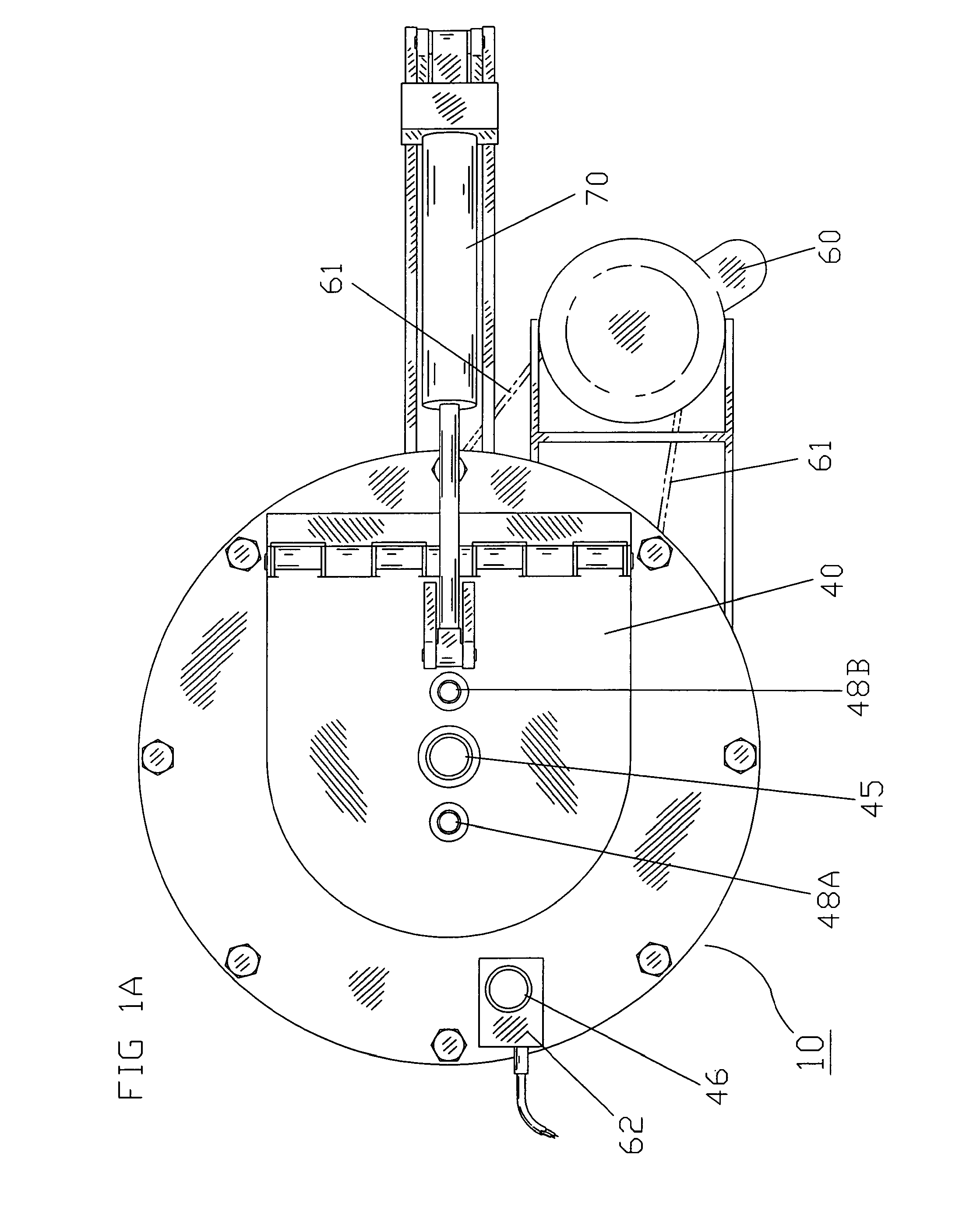
[0028]FIGS. 1-2 illustrate the preferred embodiment of the separating and dewatering system. As best shown in FIG. 1, a vertical dewatering apparatus 10 includes a slurry and inlet port 20 and a bottom hinged door 40 with seals 41 and 42. The door 40 includes a filter screen 44 and a center drain 45 and drains 48A, 48B.

[0029]The apparatus 10 has a centrally disposed perforated shaft 30, the p...


PUM

PropertyMeasurementUnit
forceaaaaaaaaaa
vertical lengthaaaaaaaaaa
areaaaaaaaaaaa

Abstract

A vertical cylindrical dewatering apparatus for dewatering fibrous slurries, slurry of manure and water, or other similar slurries. The apparatus includes a housing that includes a defined chamber having an enclosed top end with a slurry injector into the chamber, a centrally disposed first filtering element that includes first and second flightings, and a second vertical cylindrical filtering element including a support grid. The first and second filtering elements define the chamber. The slurry in-flow port at the top of the apparatus directs the slurry spiraling down between the flightings. The particles start building up at the bottom of the chamber as the water is filtered out from the housing through filtrate drains. Compressed air supplied through a rotating seal down through the centrally disposed filtering element moves through the filter, and through the particles forcing the water from between the particles out through the outer filter element. After the moisture is removed from the particles, a hinge door is opened and a drive motor turns the first filter and flightings for particle removal. An alignment ring is attached to outer edges of the lower end of said flights in order to maintain a clearance of at least ¼ inch between the outer edges and the second filter element.

Description

CROSS REFERENCES TO RELATED APPLICATIONS[0001]U.S. Provisional Application for Patent No. 61 / 268,763, filed Jun. 16, 2009, with title “Method and Apparatus for Separating and Dewatering Slurries” which is hereby incorporated by reference. Applicant claims priority pursuant to 35 U.S.C. Par. 119(e)(i).STATEMENT AS TO RIGHTS TO INVENTIONS MADE UNDER FEDERALLY SPONSORED RESEARCH AND DEVELOPMENT[0002]Not ApplicableBACKGROUND OF THE INVENTION[0003]1. Field of the Invention[0004]This invention relates to a new method for separating the particles from a slurry and dewatering them using air to remove the moisture from between the particles. This new vertical concept prevents the filter cake from becoming the main filtering element and allows the air to reduce the moisture level to previously unachievable levels.[0005]2. Brief Description of Prior Art[0006]Solid-liquid separation is one of the most worked arts in history. Never before has the need for a cost-effective mechanical dewatering p...

Claims


Application Information

Patent Timeline
Patent Type & Authority Patents(United States)
IPC IPC(8): B30B9/12B30B9/18B01D29/23B01D29/25B01D29/64B01D33/073B01D33/66
CPCB01D29/35B01D29/6476B01D29/843B01D29/94
Inventor TAPP, FLOYD G.
Owner TAPP FLOYD G
Learn More