
Systems and methods for broadband transmission of signals

a signal and broadband technology, applied in the field of signal transmission, can solve the problems of unacceptable operating performance, unacceptably high power consumption, non-linearity across the bandwidth, etc., and achieve the effect of facilitating the ability to modulate head-end equipment and facilitating the ability to utiliz

Inactive Publication Date: 2011-09-13
CSR TECH INC
View PDF16 Cites 10 Cited by
  • Summary
  • Abstract
  • Description
  • Claims
  • Application Information

AI Technical Summary

Benefits of technology

"The present invention is about a system and method that allows for the efficient transmission of signals over a network using a delivery point tuning technique. The invention utilizes a single wideband tuner for multiple pieces of equipment at a delivery point, which allows for the down conversion of signals to frequencies compatible with the equipment. The invention can transmit a variety of signal types and protocols, such as broadcast signals, narrowcast signals, and data signals, over a network in a way that is transparent to the equipment. The use of logical channels modulated in each RF channel facilitates the ability to utilize the frequency conversion and channel conversion transparently, without requiring the replacement or upgrading of legacy subscriber equipment. The invention is designed to provide efficient and reliable transmission of signals over networks, particularly those utilizing PON technology."

Problems solved by technology

Such a liner configuration is sufficiently wideband to optimize the ability to modulate multiple data streams for use at a delivery point within the tuner's bandwidth, and yet not so wideband as to present unacceptable operating performance, such as unacceptably high power consumption and non-linearity across the bandwidth.

Method used


Image

  • Systems and methods for broadband transmission of signals
  • Systems and methods for broadband transmission of signals
  • Systems and methods for broadband transmission of signals

Examples


Embodiment Construction

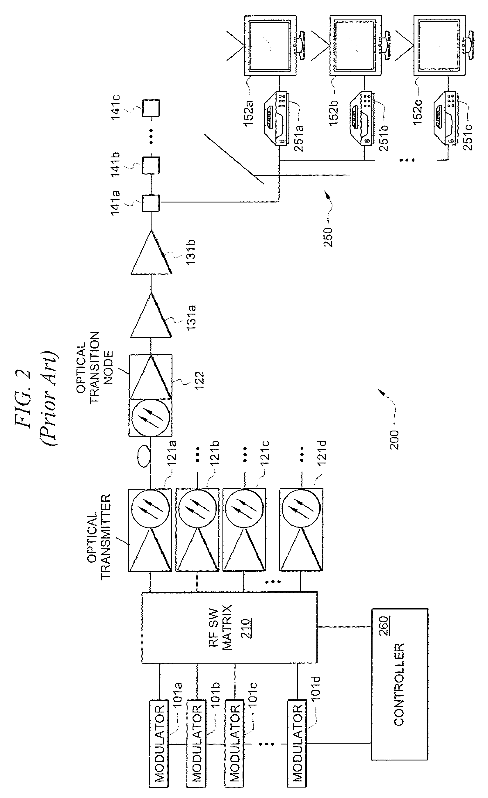
[0019]To aid in understanding the concepts of the present invention, a brief discussion of currently implemented broadband signal transmission networks is provided below. It should be appreciated that the networks shown and described, including the networks implementing embodiments of the present invention, are highly simplified (such as by illustrating only a single delivery point or subscriber site) to provide a more readily understandable illustration.

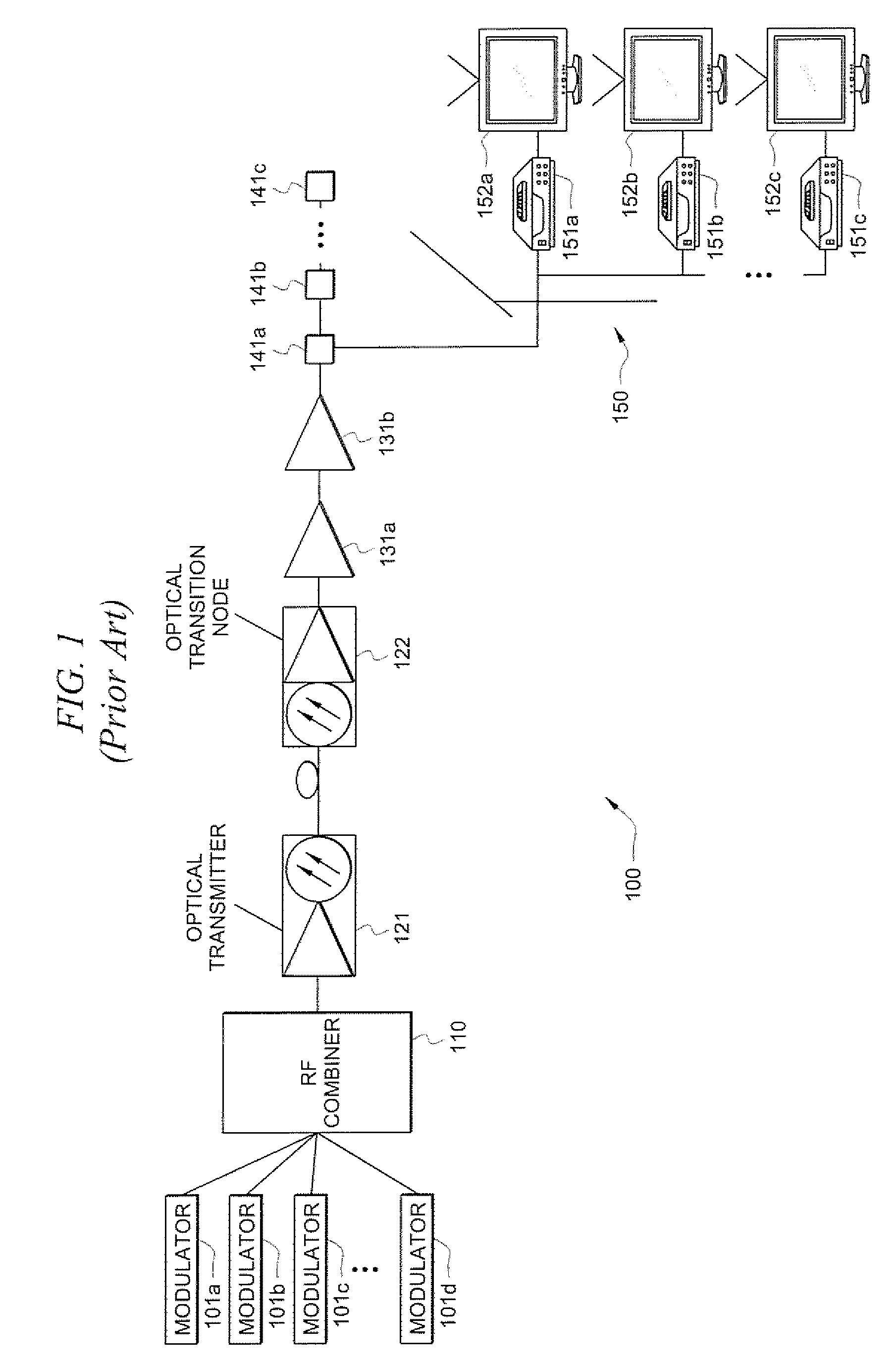
[0020]Directing attention to FIG. 1 a conventional hybrid fiber-coax (HFC) network is shown. HFC network 100 of FIG. 1 provides a broadcast architecture for broadcast transmission of approximately 1 GHz bandwidth. That is, HFC network 100 can broadcast up to 155 channels modulated in 6 MHz bands from 54 MHz to 1 GHz. Accordingly, HFC network 100 includes modulators 101a-101d each producing an output in the 54-1000 MHz band. The signals modulated by modulators 101a-101d may comprise analog signals (e.g., 1 analog signal per 6 MHz rad...


PUM


Abstract

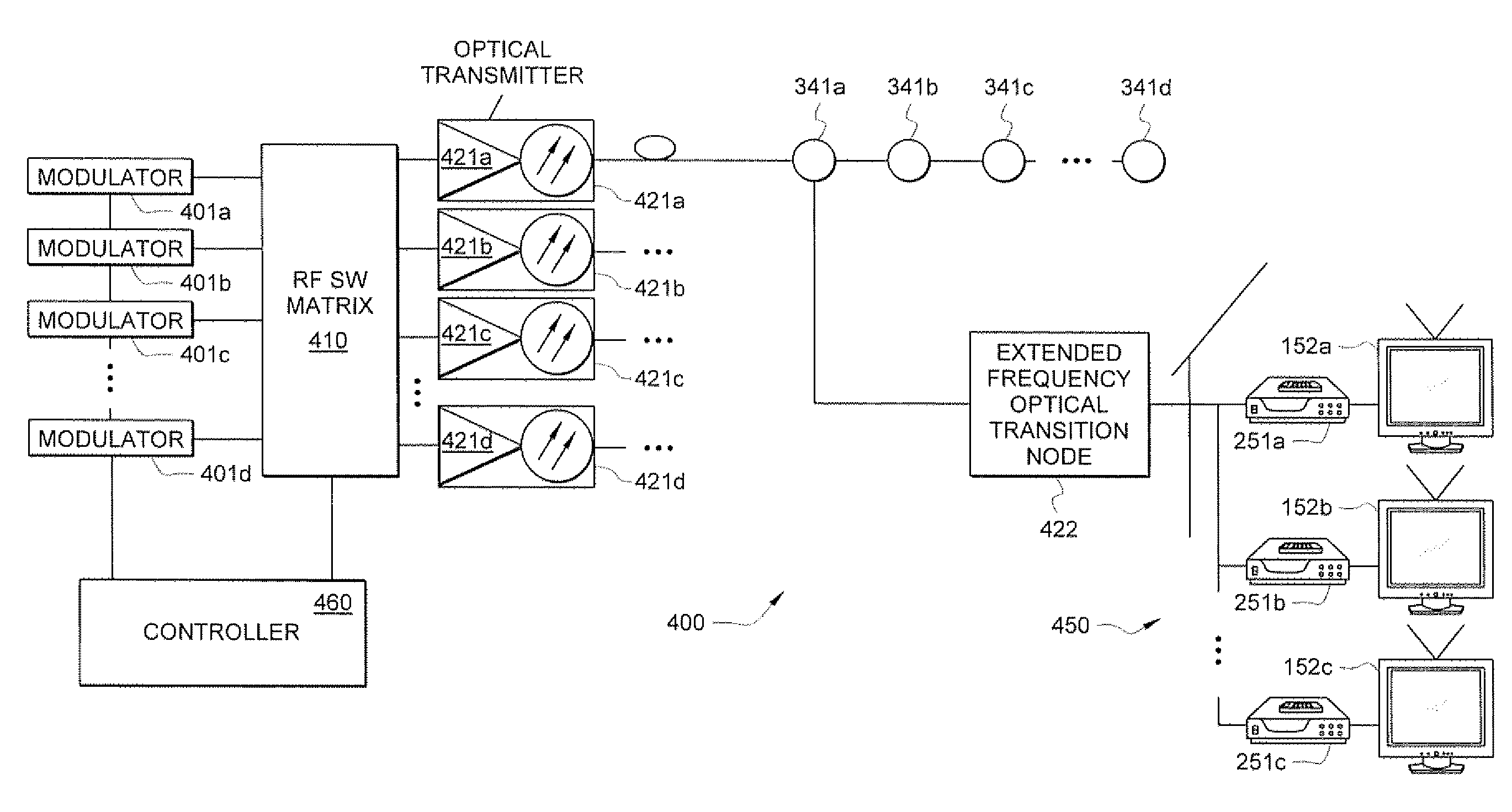
Systems and methods which facilitate broadband transmission of signals using a delivery point tuning technique to provide a extended frequency passive optical network (EF-PON) are shown. Embodiments provide an extended frequency optical transition node (EF-OTN) at each of a plurality of delivery points to provide a frequency translation interface between equipment disposed at the delivery point locations and a network utilizing transmission bandwidth which is incompatible with that equipment. The foregoing frequency conversion is preferably transparent to the equipment receiving the network transmissions. Embodiments utilize a single wideband tuner for providing frequency conversion with respect to a plurality of equipment disposed a delivery point. Network head-end modulators are controlled to implement channel grouping such that the signals requested by each piece of subscriber equipment at a delivery point are placed within radio frequency (RF) channels so that each such signal is within the frequency converted band of an EF-OTN tuner.

Description

CROSS-REFERENCE TO RELATED APPLICATIONS[0001]The present application is related to co-pending and commonly assigned U.S. patent application Ser. No. 11 / 738,825 entitled “Highly Integrated Television Tuner on a Single Microcircuit,” filed Apr. 16, 2007, Ser. No. 11 / 486,706 entitled “Broadband Integrated Tuner,” filed Jun. 29, 2006, and Ser. No. 10 / 952,185 entitled “System and Method of Eliminating or Minimizing LO-Related Interference from Multiple Tuners,” filed Sep. 28, 2004, the disclosures of which are incorporated herein by reference.TECHNICAL FIELD[0002]The invention relates generally to signal transmission and, more particularly, to broadband transmission of signals.BACKGROUND OF THE INVENTION[0003]Broadcast of television signals via cable distribution systems has been provided for a number of years. The number of channels transmitted has continued to increase over time. In recent years, the need for transmission bandwidth in the networks has not only been due to increasing te...

Claims


Application Information

Patent Timeline
Patent Type & Authority Patents(United States)
IPC IPC(8): H04J14/00
CPCH04N7/22H04B10/25751
Inventor ZANCEWICZ, GREGORY J.
Owner CSR TECH INC
Learn More