
X-ray imaging apparatus

a technology of x-ray imaging and apparatus, which is applied in the direction of instruments, patient positioning for diagnostics, applications, etc., can solve the problems of inability to obtain accurate cross-sectional image data, difficult to place the arms of the subject along the side and back surfaces of the imaging unit, and the body section from the chest to the shoulder fails to contact the front surface of the imaging uni

Inactive Publication Date: 2011-09-13
CANON KK
View PDF4 Cites 150 Cited by
  • Summary
  • Abstract
  • Description
  • Claims
  • Application Information

AI Technical Summary

Benefits of technology

The present invention is an X-ray imaging apparatus that can rotate around a subject and perform both computed tomographic (CT) imaging and still imaging. The X-ray detector has a flat rectangular detection area with short sides and long sides, and can select between two orientations. The technical effect of this invention is that it allows for more flexibility and versatility in X-ray imaging, allowing for improved image quality and efficiency in both CT imaging and still imaging.

Problems solved by technology

Further, in reconstruction of cross-sectional images in CBCT imaging, accurate cross-sectional image data may not be obtained without all projection data of cross sections of the entire body which are orthogonal to the body axis (longitudinal axis) of the subject.
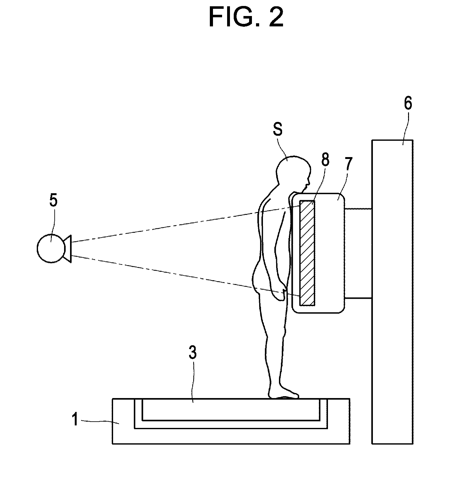
When a general X-ray imaging operation is performed to obtain an image of the chest of a patient having a small body and narrow shoulders, for example, it is difficult to place the arms of the subject along the side and back surfaces of the imaging unit.
As a result, in many cases, a body section from the chest to the shoulder fails to contact the front surface of the imaging unit.
In addition, for a patient who is not able to grab handrails provided on the back surface of the imaging unit, it is difficult to stabilize his or her body posture, which brings difficulty in obtaining a satisfactory image.

Method used


Image

  • X-ray imaging apparatus
  • X-ray imaging apparatus
  • X-ray imaging apparatus

Examples


Embodiment Construction

Preferred exemplary embodiment of the present invention will be described in detail in accordance with the accompanying drawings.

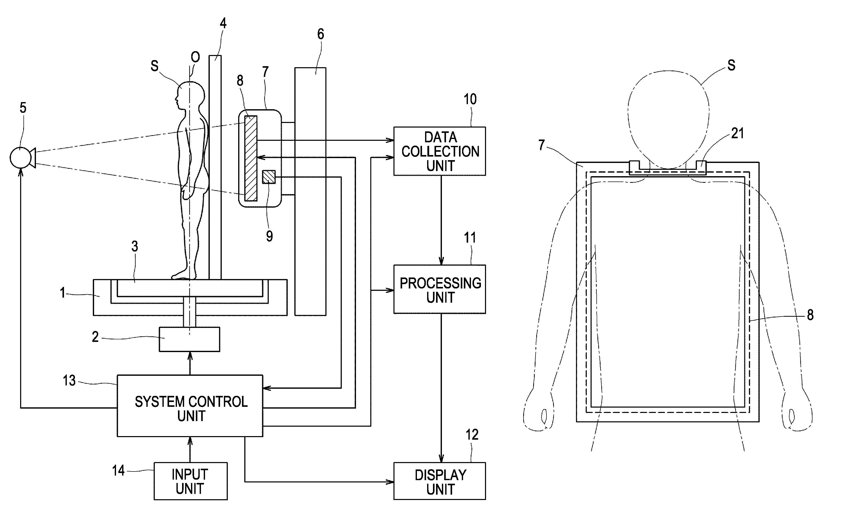
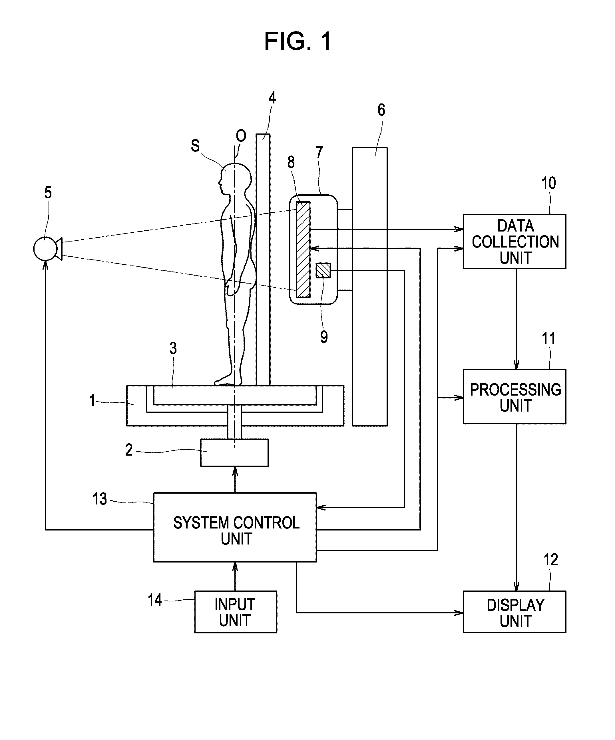
FIG. 1 illustrates CT (computed tomographic) imaging performed by an X-ray imaging apparatus according to an exemplary embodiment of the present invention. A subject mount 1 has a turntable 3 mounted thereon which serves as rotation driving means driven by a driving unit 2. The turntable 3 is disposed so as to be rotatable about a rotation center O and is provided with a detection mechanism (not shown) for detecting the angle, position and the rotation speed of the turntable 3. The driving unit2 supplies torque to the turntable 3, enabling starting, acceleration, deceleration, and stopping of the turntable 3. A subject supporting member 4 is disposed on the turntable 3 for supporting and fixing a subject S at a position which generally coincides with a rotation axis O. A part of the subject supporting member 4 corresponding to an X-ray irradiation area is ...


PUM


Abstract

An X-ray imaging apparatus includes an imaging unit which is rotatable relative to a platform about a shaft portion perpendicular to an X-ray detecting surface, so as to change the orientation relative to a subject.

Description

BACKGROUND OF THE INVENTION1. Field of the InventionThe present invention relates to X-ray imaging apparatuses for acquiring X-ray images from X-rays transmitted through imaging subjects.2. Description of the Related ArtIn an X-ray imaging apparatus in general, an X-ray generator and an imaging unit containing an X-ray detector are disposed so as to face each other, and imaging is performed by arranging a subject to be imaged such as a human body between the X-ray generator and the imaging unit. In X-ray imaging, a position of the imaging unit relative to the X-ray generator and the subject is determined and then the subject is irradiated with X-rays to obtain necessary X-ray images.With the recent advances in the speed of image processing apparatuses, apparatuses capable of capturing moving images and three-dimensional images in addition to two-dimensional still images have gradually become commercially available. To obtain three-dimensional images, dedicated computed tomography ap...

Claims


Application Information

Patent Timeline
Patent Type & Authority Patents(United States)
IPC IPC(8): H05G1/58
CPCA61B6/032A61B6/035A61B6/04A61B6/4441A61B6/587A61B6/4423
Inventor KATO, KATSUSHI
Owner CANON KK
Learn More