
Ternary valve input circuit

a technology of input circuit and ternary value, which is applied in the direction of logic circuit, logic circuit, logic circuit characterised by logic function, etc., can solve the problems of complex design, increased device area, and unstable operation of ternary value input circui

Active Publication Date: 2011-09-06
SEMICON COMPONENTS IND LLC
View PDF24 Cites 5 Cited by
  • Summary
  • Abstract
  • Description
  • Claims
  • Application Information

AI Technical Summary

Problems solved by technology

This resulted in a problem of increased device area due to setting a desired threshold voltage at each transistor.
Furthermore, since it is necessary to complementarily connect each transistor, a problem also results where the operation of the ternary value input circuit becomes unstable when the threshold voltage fluctuates.
In addition, there is also a problem of a complex design since it is necessary to take into consideration the fluctuation of the threshold voltage of each transistor.

Method used


Image

  • Ternary valve input circuit
  • Ternary valve input circuit
  • Ternary valve input circuit

Examples


modified example 1

[0045]In the configuration of the ternary value input circuit 100 in the above-mentioned embodiment, frequent switching of pull-up and pull-down causes current to flow via the pull-up transistor 20 or the pull-down transistor 22 as shown by the current at the input terminal in FIG. 4 and increases the power consumption of the circuit.

[0046]Consequently, it is preferable to generate the enable signal ENABLE and the pull signal PULL with a signal generator circuit 200 shown in FIG. 5.

[0047]The signal generator circuit 200 includes a counter 36, a first selector 38, a second selector 40, and flip-flops 42 and 44. The counter 36 receives the system clock CLK, cyclically counts from 0 to a predetermined value, and outputs the counter value. In the embodiment, the counter 36 counts up from 0 to 63, returns the counter value from 63 to 0, and repeats the count up. The first selector 38 receives the counter value output from the counter 36 and outputs a high level (H) when the counter value...

modified example 2

[0051]It is preferable to generate the enable signal ENABLE and the pull signal PULL with a signal generator circuit 300 shown in FIG. 8.

[0052]The signal generator circuit 300 includes the counter 36, the first selector 38, the flip-flops 42 and 44, and a third selector 46. Since the signal generator circuit 300 is identical to the signal generator circuit 200 except for the third selector 46, mainly the operation of the third selector 46 will be described hereinafter.

[0053]The third selector 46 receives the counter value output from the counter 36, the output signal QUP of the pull-up output circuit 28, and a feedback signal of the output PULL of the flip-flop 42, and outputs the output signal QUP when the value of the counter is the first value plus 2, outputs a low level when the value of the counter is the first value plus 1, and outputs the feedback signal otherwise.

[0054]For example, when the first value is 62, a low level (L) is output when the counter value is 63, which is t...


PUM


Abstract

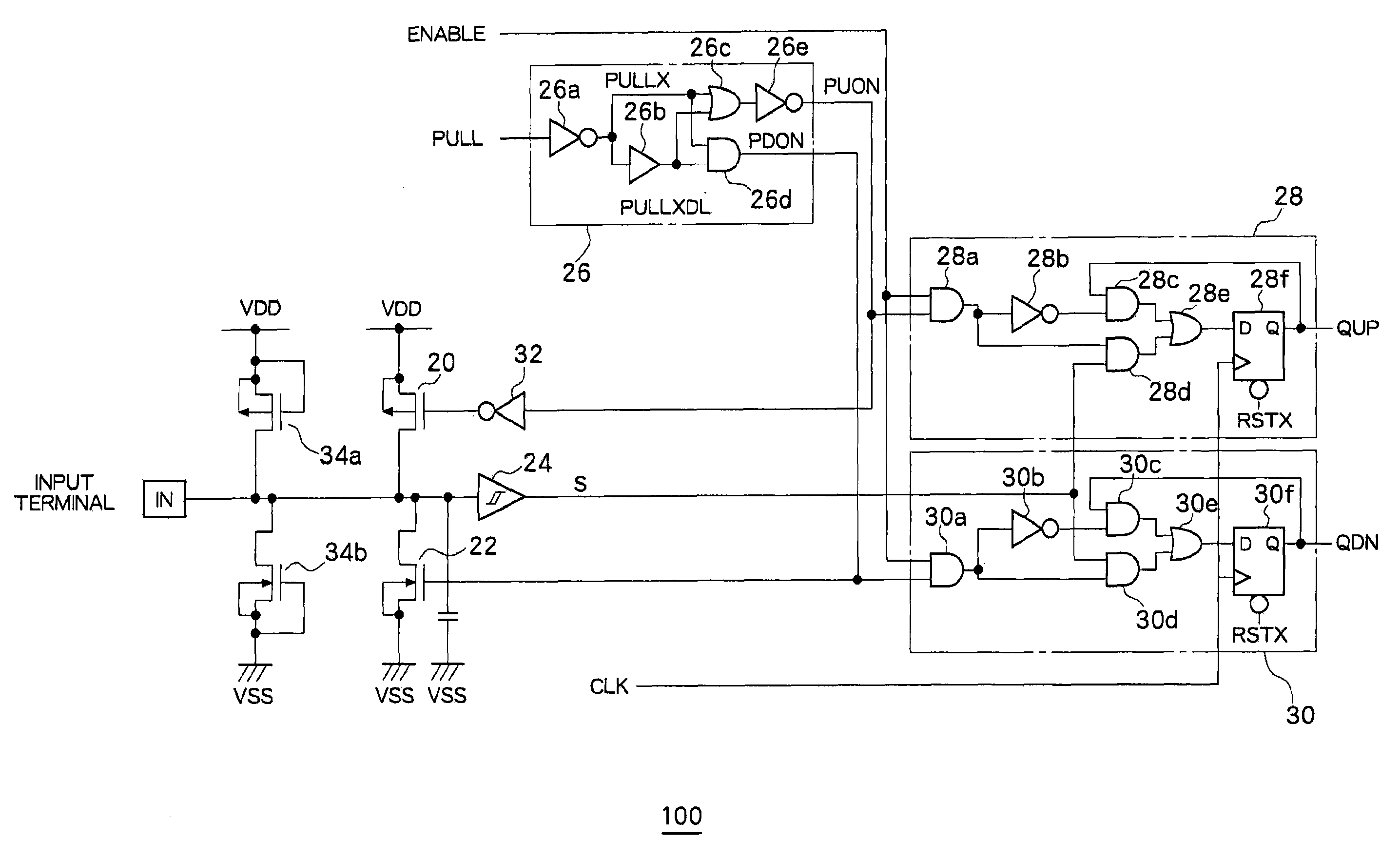
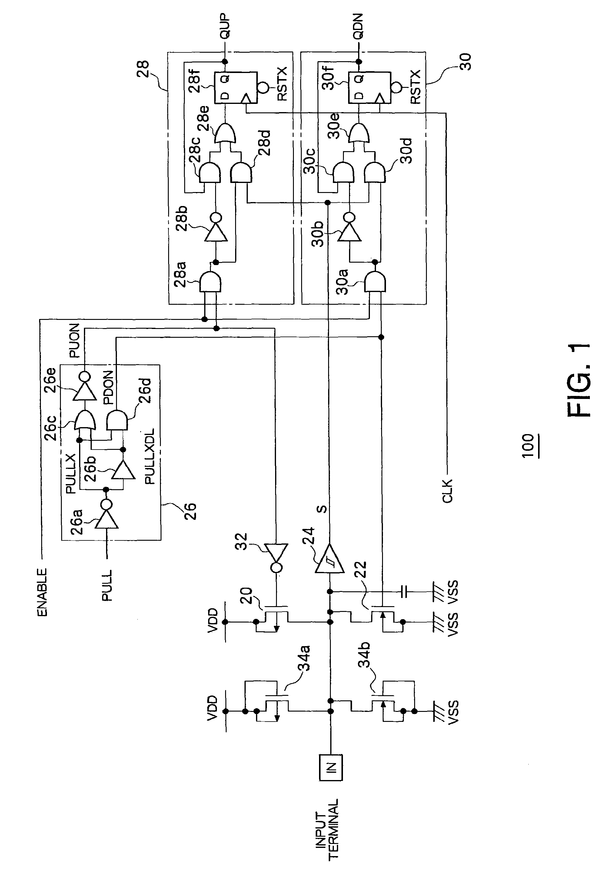
A pull-up switching device for controlling connection and non-connection of an input terminal IN and a first supply VDD and a pull-down switching device for controlling connection and non-connection of the input terminal IN and a second supply VSS are provided. The pull-up switching device and the pull-down switching device are operated exclusively on and off in time division to hold and output the state of the input terminal during each operating state from the two output terminals.

Description

CROSS-REFERENCE TO RELATED APPLICATIONS[0001]The entire disclosure of Japanese Patent Application No. 2008-154833 including specifications, claims, drawings, and abstract is incorporated herein by references.BACKGROUND OF THE INVENTION[0002]1. Field of the Invention[0003]The present invention relates to a ternary value input circuit for digitally realizing ternary value inputs.[0004]2. Description of the Related Art[0005]Ternary value input circuits are known for communicating input terminal states of high level, low level, and open as a level of an output terminal level.[0006]For example, a ternary value input circuit disclosed in FIG. 11 is composed of a voltage divider circuit formed from resistors 10 and 12 connected to an input terminal IN and two inverter circuits 14 and 16 having different threshold voltages.[0007]The first inverter circuit 14 is formed from a P-channel field-effect transistor 14a and an N-channel field-effect transistor 14b and the second inverter circuit 16...

Claims


Application Information

Patent Timeline
Patent Type & Authority Patents(United States)
IPC IPC(8): H03K19/00H03K19/02
CPCH03K19/0002H03K19/09425H03K19/08H03K19/20
Inventor ITO, HIDEO
Owner SEMICON COMPONENTS IND LLC
Learn More