
Ultra thin TCS (SiCl4) cell nitride for DRAM capacitor with DCS (SiH2Cl2) interface seeding layer

a dram capacitor and dcs technology, applied in the direction of coatings, transistors, basic electric elements, etc., can solve the problems of poor electrical quality of the high temperature nitridated layer, low thickness, and extremely slow growth of the nitride, so as to improve the cp-leakage performance and achieve the same electrical performance. , the effect of saving the thermal budget for other processes

Inactive Publication Date: 2011-09-06
MICRON TECH INC
View PDF45 Cites 4 Cited by
  • Summary
  • Abstract
  • Description
  • Claims
  • Application Information

AI Technical Summary

Benefits of technology

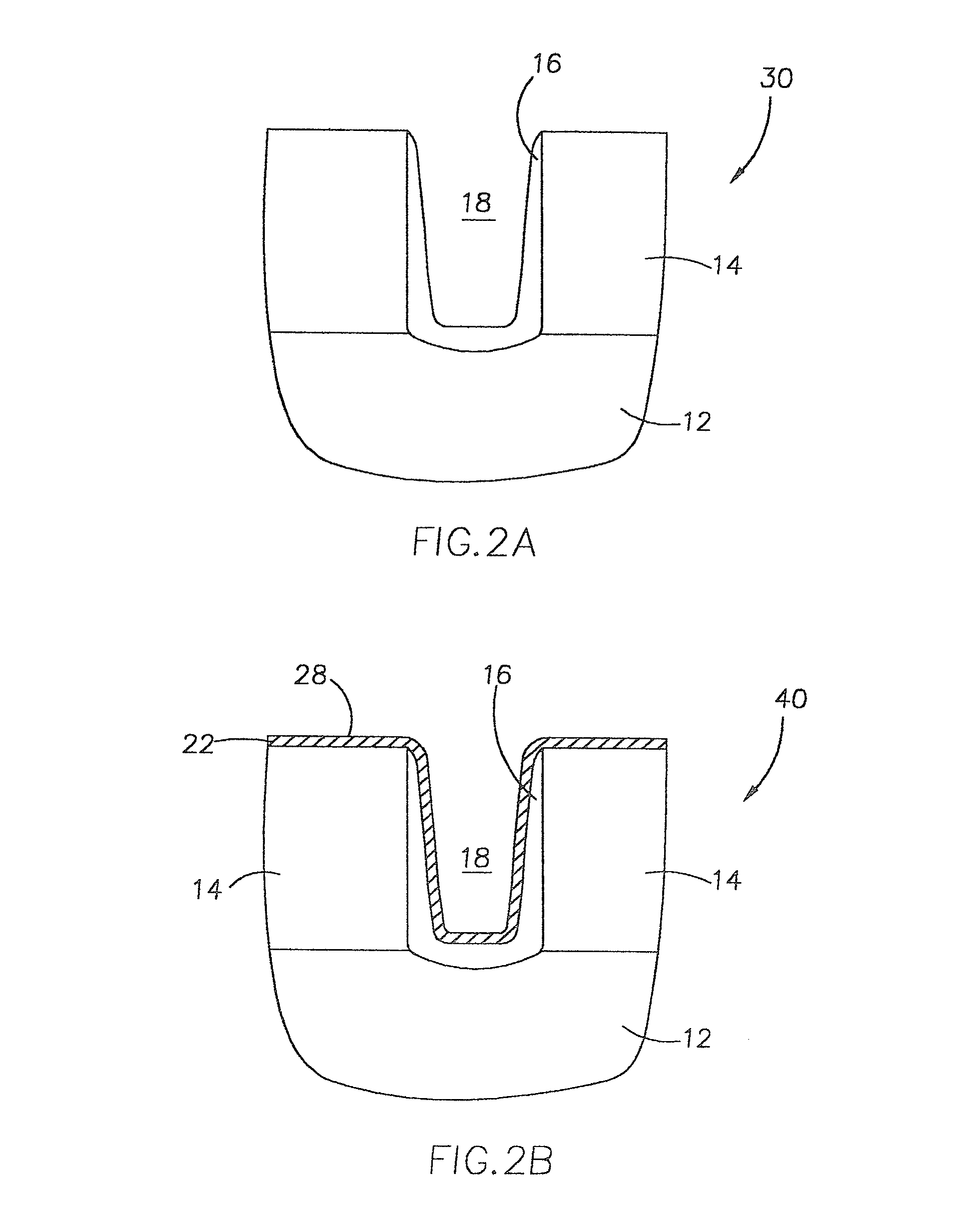
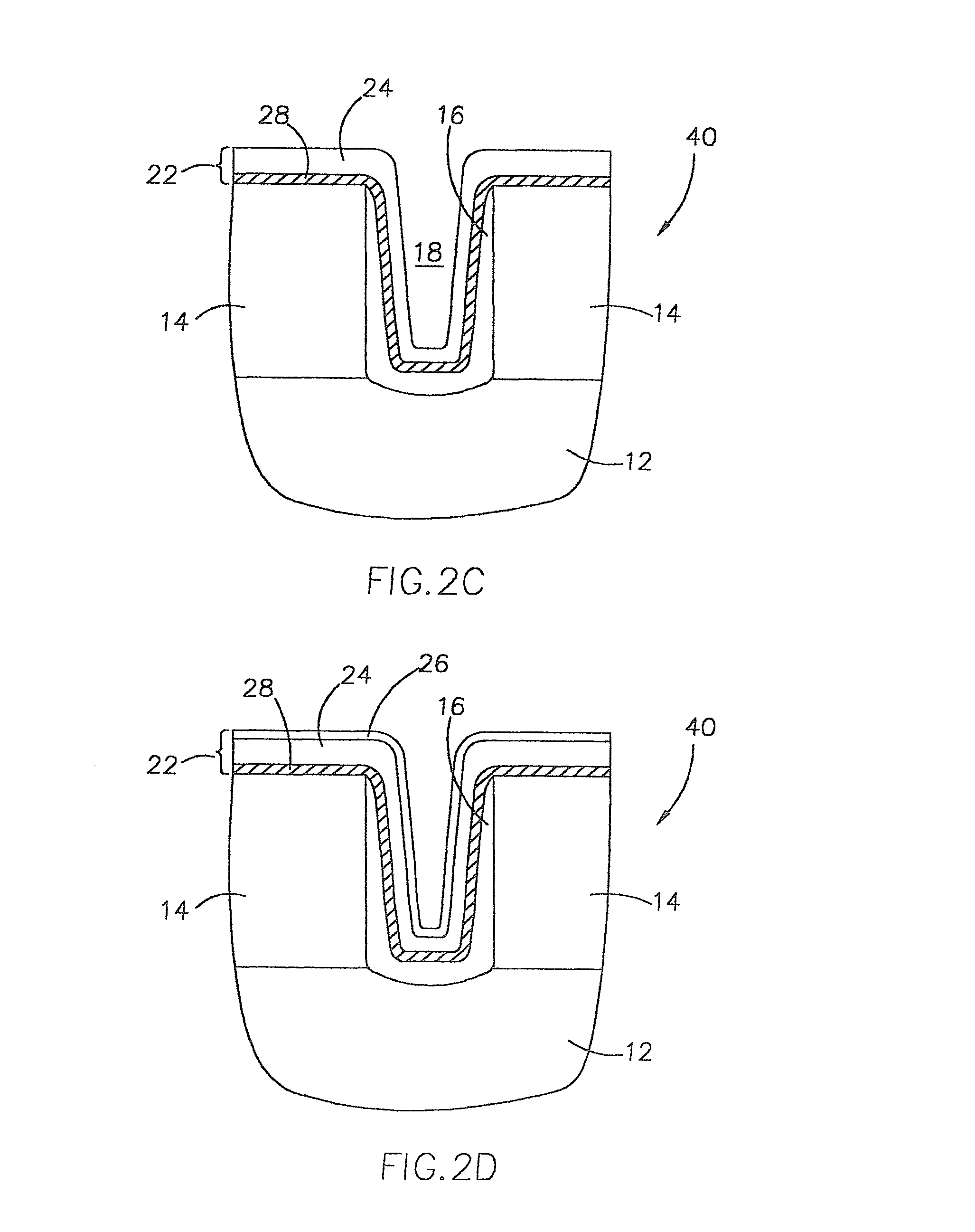
[0015]The present invention combines depositing a DCS nitride seeding layer with depositing a TCS nitride layer on a silicon-comprising substrate to improve the thickness of a dielectric silicon nitride layer deposited using TCS on silicon-comprising substrates of a semiconductor device being constructed. Before the deposition of the TCS nitride, a thin layer of DCS nitride is deposited as an interface “seeding layer” on the surface of the silicon-comprising substrate for the formation of the TCS nitride layer such as by low pressure chemical vapor deposition (LPCVD). Advantageously, the DCS seeding layer can be deposited without a conventionally used NH3 pre-anneal nitridation step, by utilizing a pressure of about 1-3 Torr in the reaction chamber.
[0024]Semiconductor devices fabricated with the silicon nitride deposition method according to the present invention to provide a DCS / TCS nitride layer, have substantially the same electrical performance as a conventional device fabricated with a silicon nitride layer made of TCS nitride alone, and improved Cp-leakage performance over a device made with a DCS nitride layer alone. Also, with the use of the DCS seeding layer, the nucleation and deposition rate of the TCS nitride component upon the substrate is substantially equivalent regardless of the silicon-comprising material that constitutes the substrate. This alleviates the problem of different or degraded electrical characteristics that result from the differences in the nitride thickness deposited on adjacent surfaces. Such differences are especially apparent, for example, between a conductor composed of silicon, and an insulator composed of TEOS, where a relatively thin nitride layer deposited at a silicon / TEOS edge can result in degraded electrical properties at that edge and for the resulting fabricated device.
[0025]The use of the DCS / TCS nitride layer also resolves the fatal BPSG bubbling problem that occurs with TCS nitride layers that are deposited directly on BPSG substrates in semiconductor devices. Additionally, the elimination of a high temperature NH3 pre-anneal step from the process conserves the thermal budget for other processes in the fabrication operation.

Problems solved by technology

However, the growth of the nitride is extremely slow and self-limiting since the NH3 is not capable of adequately diffusing through the growing silicon nitride layer to react with the underlying silicon.
Such thickness is usually too low to adequately function as a barrier to prevent further oxidation of the silicon surface during subsequent processing, or as a capacitor dielectric layer between two conductive capacitor plates.
Further, the electrical quality of this high temperature nitridated layer is poor.
The drawbacks of these methods include poor electrical performance of the RTN / DCS layer and high thermal budget induced from the high temperature RTN process.
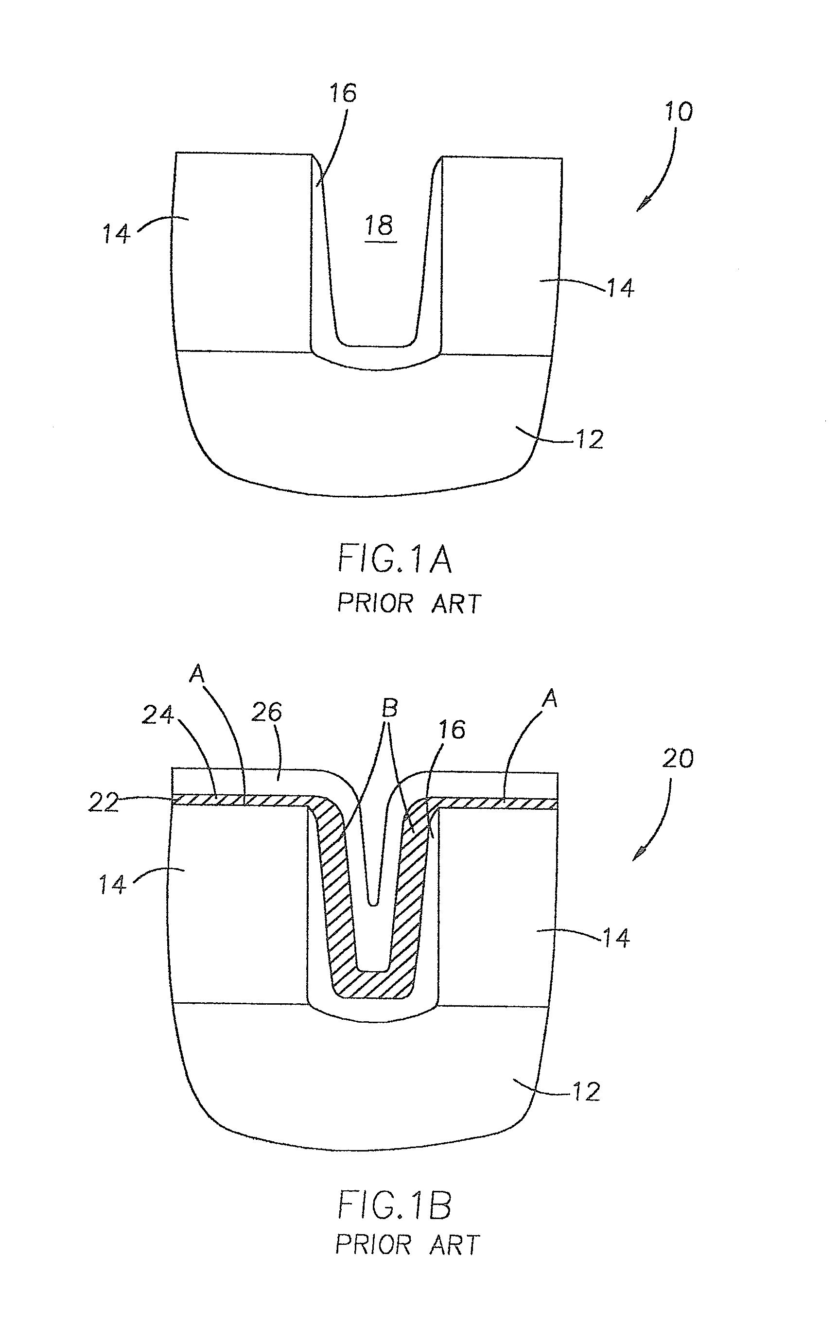
However, there have been problems with nucleation of TCS nitride on certain silicon-based surfaces such as borophosphosilicate glass (BPSG) using current TCS cell nitride processes.
At a thickness of less than about 20 angstroms, the nitride is not able to prevent the polysilicon electrode from becoming oxidated in the wet re-oxidation step that follows the cell nitride deposition.
These bubblings are fatal physical defects and will result in massive fail of the part.
The poor nucleation of TCS nitride on BPSG has limited the use of TCS nitride to below about 50 angstroms in current DRAM capacity modules.

Method used


Image

  • Ultra thin TCS (SiCl4) cell nitride for DRAM capacitor with DCS (SiH2Cl2) interface seeding layer
  • Ultra thin TCS (SiCl4) cell nitride for DRAM capacitor with DCS (SiH2Cl2) interface seeding layer
  • Ultra thin TCS (SiCl4) cell nitride for DRAM capacitor with DCS (SiH2Cl2) interface seeding layer

Examples


example

[0061]DCS nitride and TCS nitride were deposited, alone and in combination, on a BPSG substrate to compare the measured thicknesses of the nitride layer and Cp-leakage performance.

[0062]There was a 10-minute NH3 pre-anneal before the DCS seeding layer deposition. The time period of the NH3 pre-anneal included a ramp-up time from 300° C. to 800° C. The DCS and TCS nitride depositions were at about 640° C. with pressure of 0.15 Torr and 0.2 Torr, respectively. After the cell nitride deposition, all wafers went through a standard wet re-oxidation (750° C., 105 Å target on Si blank test wafer).

[0063]The experimental details and results are shown below in Table 1 and depicted in FIGS. 4A-4F and FIG. 5. The results show that the deposition of a silicon nitride layer utilizing a DCS nitride seeding layer for TCS nitride offers the same electrical performance as a TCS nitride layer, and solves the “bubbling” problem of deposition of TCS nitride on BPSG in DRAM devices.

[0064]

TABLE 1AmountNit...


PUM

PropertyMeasurementUnit
thicknessaaaaaaaaaa
thicknessaaaaaaaaaa
thicknessaaaaaaaaaa

Abstract

A method for forming silicon nitride films on semiconductor devices is provided. In one embodiment of the method, a silicon-comprising substrate is first exposed to a mixture of dichlorosilane (DCS) and a nitrogen-comprising gas to deposit a thin silicon nitride seeding layer on the surface, and then exposed to a mixture of silicon tetrachloride (TCS) and a nitrogen comprising gas to deposit a TCS silicon nitride layer on the DCS seeding layer. In another embodiment, the method involves first nitridizing the surface of the silicon-comprising substrate prior to forming the DCS nitride seeding layer and the TCS nitride layer. The method achieves a TCS nitride layer having a sufficient thickness to eliminate bubbling and punch-through problems and provide high electrical performance regardless of the substrate type. Also provided are methods of forming a capacitor, and the resulting capacitor structures.

Description

CROSS-REFERENCE TO RELATED APPLICATIONS[0001]This application is a continuation of U.S. patent application Ser. No. 09 / 922,628, filed Aug. 6, 2001, which is a division of U.S. patent application Ser. No. 09 / 653,523, filed Aug. 31, 2000.TECHNICAL FIELD[0002]The present invention relates to the fabrication of integrated circuit devices, and more particularly, to methods of forming silicon nitride layers on silicon-comprising substrate surfaces, methods of forming capacitors, and to capacitor constructions.BACKGROUND OF THE INVENTION[0003]Silicon nitride (Si3N4) layers are frequently used in the fabrication of semiconductor wafers, for example, in the fabrication of MOSFET gates, memory cells, and precision capacitors. Silicon nitride layers are utilized as an insulation layer over silicon surfaces to electrically isolate conductive components of a semiconductor circuit from one another. Silicon nitride films are also used as a diffusion barrier to protect regions of a semiconductor wa...

Claims


Application Information

Patent Timeline
Patent Type & Authority Patents(United States)
IPC IPC(8): H01L27/108H01L21/318H01L23/58C23C16/02C23C16/34H01L21/3105H01L21/314
CPCC23C16/0272C23C16/345H01L21/31051H01L21/3115H01L21/3185H01L21/3211H01L29/94H01L2924/0002H01L2924/00H01L21/02271H01L21/02211H01L21/0217
Inventor ZHENG, LINGYI APING, ER-XUAN
Owner MICRON TECH INC
Learn More