
Magnetic recording medium, process for producing same, and magnetic recording reproducing apparatus

a recording medium and magnetic recording technology, applied in data recording, thin material processing, instruments, etc., can solve the problems of stacking faults in the crystalline structure at the step of layers, the upper limit of line recording density, and the thickness of the magnetic recording medium is larger. achieve the effect of enhancing the recording density characteristic and minimizing the angle variation

Active Publication Date: 2011-09-06
TOHOKU UNIV +2
View PDF11 Cites 2 Cited by
  • Summary
  • Abstract
  • Description
  • Claims
  • Application Information

AI Technical Summary

Benefits of technology

[0045]The perpendicular magnetic recording medium according to the present invention has a perpendicular magnetic recording layer with a crystalline structure wherein the crystal c-axis in a hcp structure is oriented perpendicularly to the surface of substrate with a minimized angle variation, and the crystal grains constituting the perpendicular magnetic recording layer have a uniform grain diameter and an extremely small average grain diameter, and which exhibits highly enhanced recording density characteristic.

Problems solved by technology

This undesirable phenomenon puts an upper limit on the line recordation density.
However, a perpendicular magnetic recording medium has a problem such that the total thickness of the magnetic recording medium is larger than that of the conventional longitudinal magnetic recording medium, although the perpendicular magnetic recording medium is advantageous in that the thickness of a magnetic recording layer can be relatively large.
The formation of the perpendicular magnetic recording medium having a large thickness easily causes stacking faults in the crystalline structure at the steps of layers.
However, in the case when the seed layer is comprised of an amorphous material, the crystal grains in the magnetic recording layer are not uniform in diameter and have large distribution of grain diameters.
In the case when the seed layer is formed from a fcc crystal material, the size of crystal grains in the magnetic recording layer is difficult to control.
Thus, the seed layer comprised of an amorphous material or a crystalline material with a fcc structure is difficult to give a magnetic recording medium having a satisfying recording and reproducing characteristics.

Method used


Image

  • Magnetic recording medium, process for producing same, and magnetic recording reproducing apparatus
  • Magnetic recording medium, process for producing same, and magnetic recording reproducing apparatus
  • Magnetic recording medium, process for producing same, and magnetic recording reproducing apparatus

Examples


example 1

Comparative Example 1

[0098]A glass substrate for HD was placed in a vacuum chamber and the chamber was evacuated to a reduced pressure of below 1.0-10−5 Pa.

[0099]A soft magnetic layer comprised of CoNbZr and having a thickness of 50 nm was formed on the glass substrate. The formation of the soft magnetic layer was carried out by a sputtering method at a reduced pressure of 0.6 Pa in an argon atmosphere.

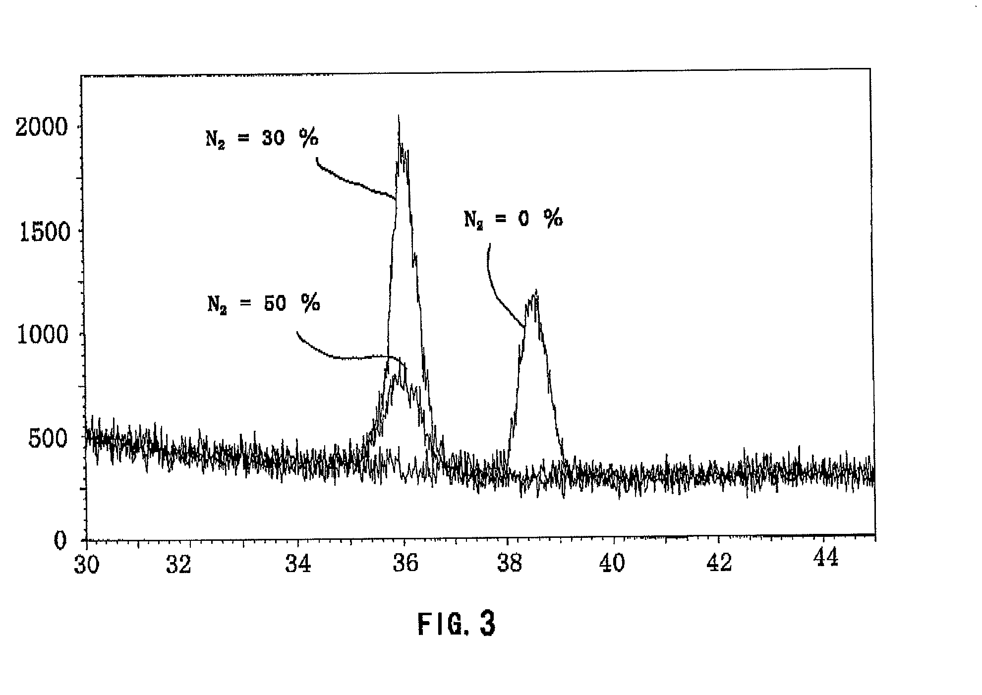
[0100]A seed layer comprised of AlN as a covalently bonded material was formed on the soft magnetic layer by reactive sputtering. The reactive sputtering was carried out using aluminum target and N2 gas and argon gas. The relative volume rate in flow of N2 gas to argon gas was 0%, 10%, 20%, 30%, 40% and 50% in Comparative Examples 1-1 to 1-3 and Examples 1-1 to 1-3, respectively. The total gas pressure (Ar+N2) was maintained at 0.6 Pa. As the volume rate in flow of N2 gas is increased, the rate of deposition of aluminum thin film is reduced. Therefore, the relationship between the vol...

example 2

Comparative Example 2

[0115]By the same procedures as described in Example 1-1, a soft magnetic layer was formed on a glass substrate, and then a seed layer comprised of AlN as a covalently bonded material was formed on the soft magnetic layer by reactive sputtering. The total gas pressure (Ar+N2) was maintained at 0.6 Pa. The relative volume rate in flow of N2 gas to argon gas was 30%. Thus, seed layers having different thicknesses were formed (thickness: 5.0, 7.5 and 10.0 nm in Examples 2-1 to 2-3). On the seed layer, an underlayer, a magnetic recording layer and an overcoat were formed in turn by the same procedures as described in Example 1. All other conditions remained the same.

[0116]For comparison, comparative specimen were made by the same procedures as mentioned above except that the seed layer was formed from a different material as follows. All other procedures and conditions remained the same.

[0117]In Comparative Examples 2-1 to 2-3, a seed layer comprised of Cu having a ...

example 3

[0130]By the same procedures as described in Example 1-1, a soft magnetic layer comprised of CoNbZr and having a thickness of 50 nm was formed on a glass substrate at a reduced pressure of 0.6 Pa in an argon atmosphere. Thereafter, the soft magnetic layer-formed substrate was heated. The heating time of the soft magnetic layer-formed substrate was varied (0, 3, 6 or 9 seconds in Examples 3-1, 3-2, 3-3 and 3-4, respectively) so as to vary the temperature thereof on which the seed layer is to be formed. Then, a seed layer comprised of AlN as a covalently bonded material and having a thickness of 10.0 nm was formed on the heated soft magnetic layer by reactive sputtering. The total gas pressure (Ar+N2) was maintained at 0.6 Pa. The relative volume rate in flow of N2 gas to argon gas was 30%. On the seed layer, an underlayer, a magnetic recording layer and an overcoat were formed in turn by the same procedures as described in Example 1. All other conditions remained the same.

[0131]The t...


PUM

PropertyMeasurementUnit
average crystal grain diameteraaaaaaaaaa
thicknessaaaaaaaaaa
total thicknessaaaaaaaaaa

Abstract

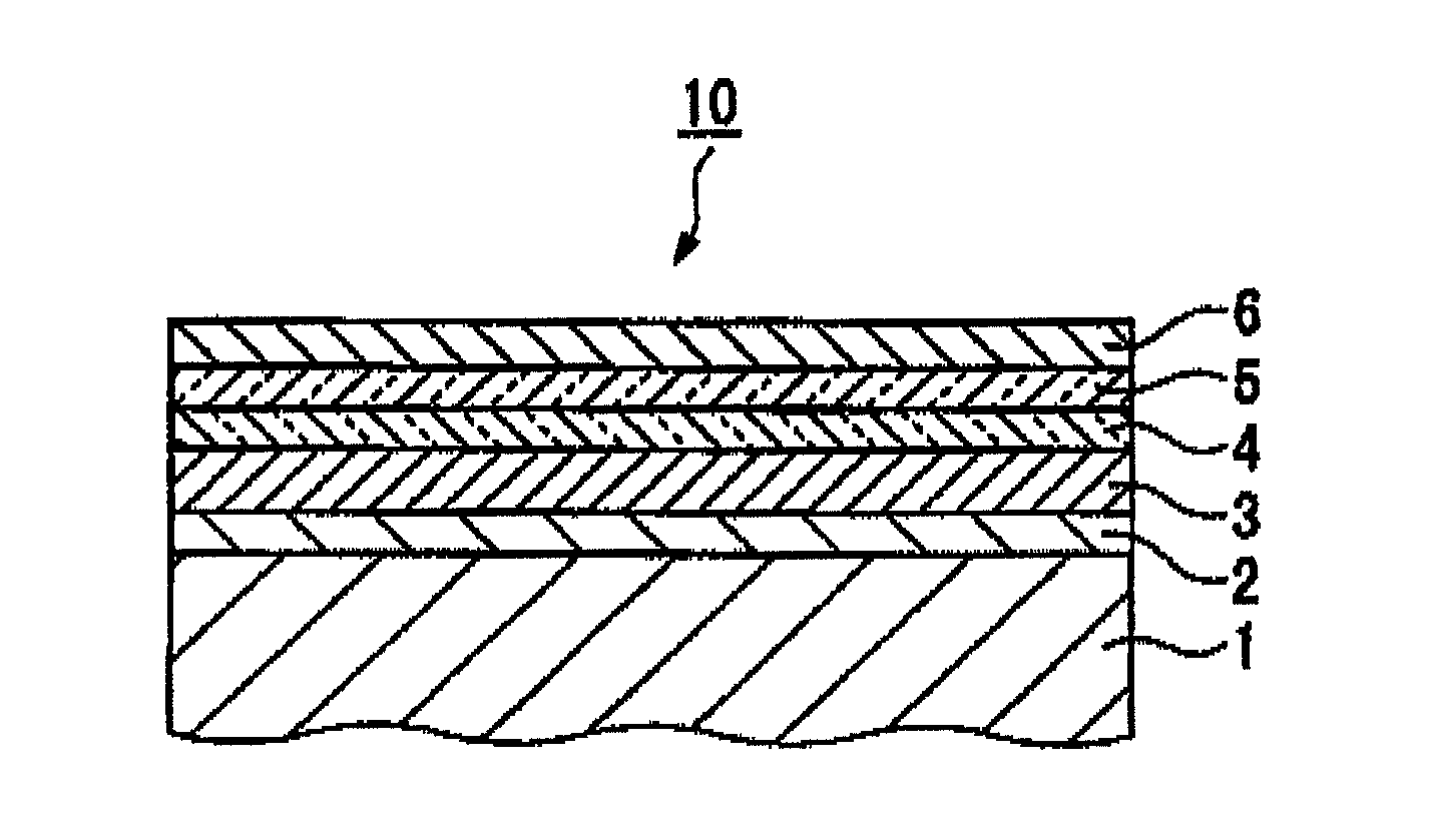
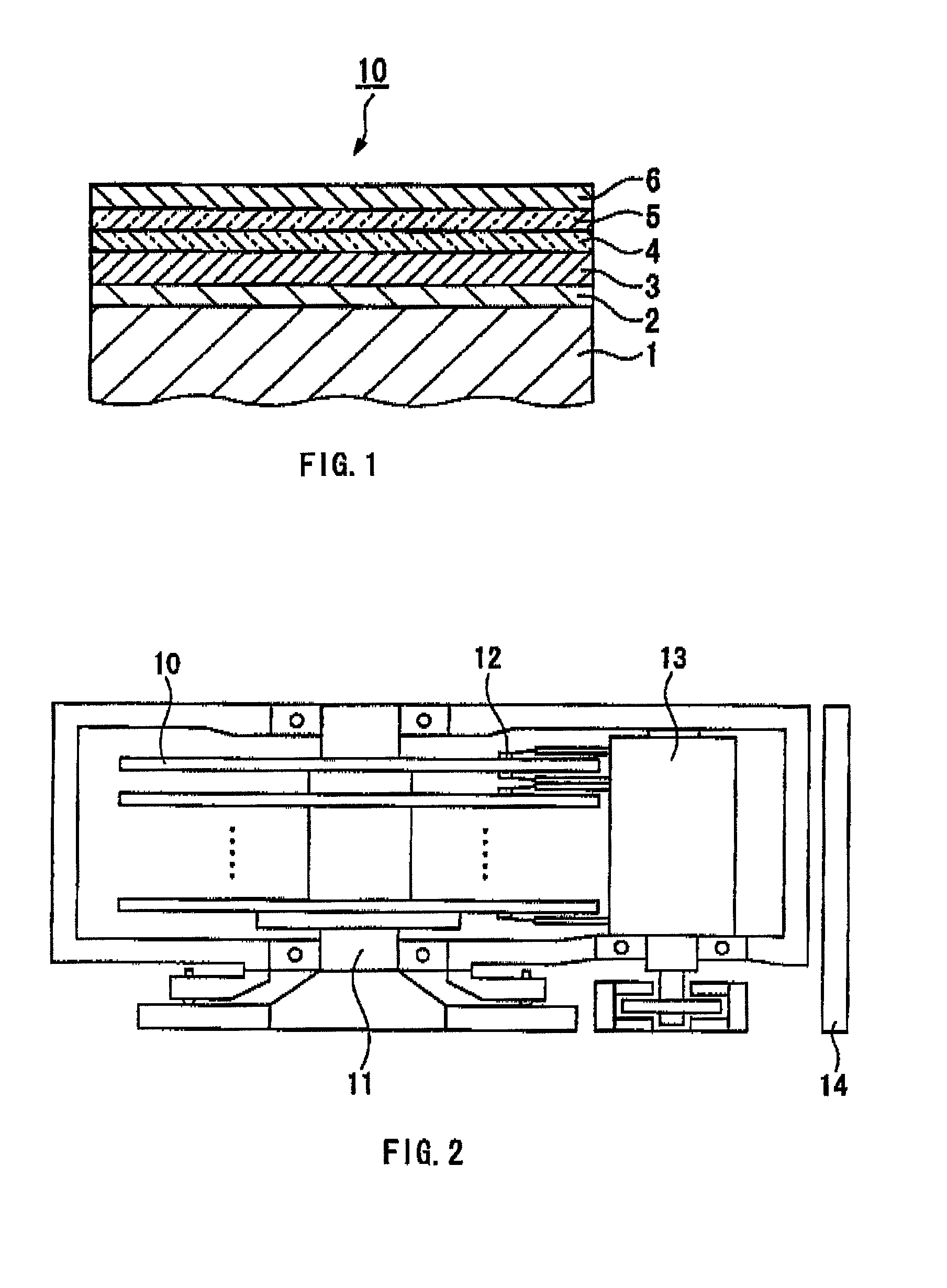
A magnetic recording medium is provided, which has at least one soft magnetic layer, at least one seed layer, at least one underlayer and at least one perpendicular magnetic recording layer, and is characterized in that the or each seed layer is comprised of a covalently bonded material. The covalently bonded material preferably predominantly comprises a nitride having a hexagonal crystal structure, more preferably, predominantly comprises aluminum nitride having a hexagonal wurtzite crystal structure. This magnetic recording medium is superior in recording and reproducing an information with high density.

Description

TECHNICAL FIELD[0001]This invention relates to a magnetic recording medium, a process for producing the magnetic recording medium, and a magnetic recording reproducing apparatus provided with the magnetic recording medium.BACKGROUND ART[0002]In recent years, magnetic recording apparatuses such as a magnetic disk apparatus, a flexible disk apparatus and a magnetic tape apparatus are widely used and their importance is increasing. Recording density of a magnetic recording medium used in the magnetic recording apparatuses is greatly enhanced. Especially, since the development of MR head and PRML technique, the areal recording density is more and more increasing. Recently GMR head and TuMR head have been developed, and the rate of increase in the plane recording density is very remarkable.[0003]There is still increasing a demand for further enhancing the recording density in magnetic recording media, and therefore, a magnetic layer having a higher coercive force and a higher signal-to-n...

Claims


Application Information

Patent Timeline
Patent Type & Authority Patents(United States)
IPC IPC(8): G11B5/66
CPCG11B5/732Y10T428/11G11B5/7379
Inventor TAKAHASHI, MIGAKUSAITO, SHINMAEDA, TOMOYUKITAKEO, AKIHIKOSASAKI, YUZOSAKAGUCHI, RYUJI
Owner TOHOKU UNIV
Learn More