
Turbine blade nested seal and damper assembly

a technology of damper assembly and turbine blade, which is applied in the direction of liquid fuel engines, vessel construction, marine propulsion, etc., to achieve the effects of less complicated and stronger, less expensive, and convenient manufacturing

Active Publication Date: 2011-09-06
RTX CORP
View PDF21 Cites 37 Cited by
  • Summary
  • Abstract
  • Description
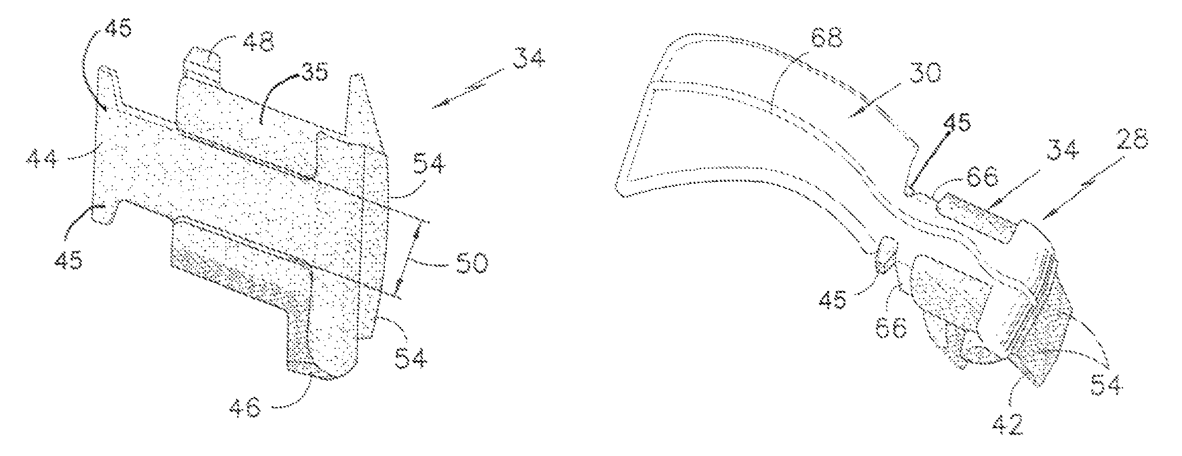
  • Claims
  • Application Information

AI Technical Summary

Benefits of technology

[0007]The damper provides dampening, and unlike traditional interplatform turbine blade dampers, also provides sealing. The damper also includes features that cause entrapment between blades and therefore avoids the conventionally required protrusions on the blade for retention in the assembled position. Minimization or elimination of such blade protrusions facilitates manufacture of a less complicated and stronger, yet less expensive blade.
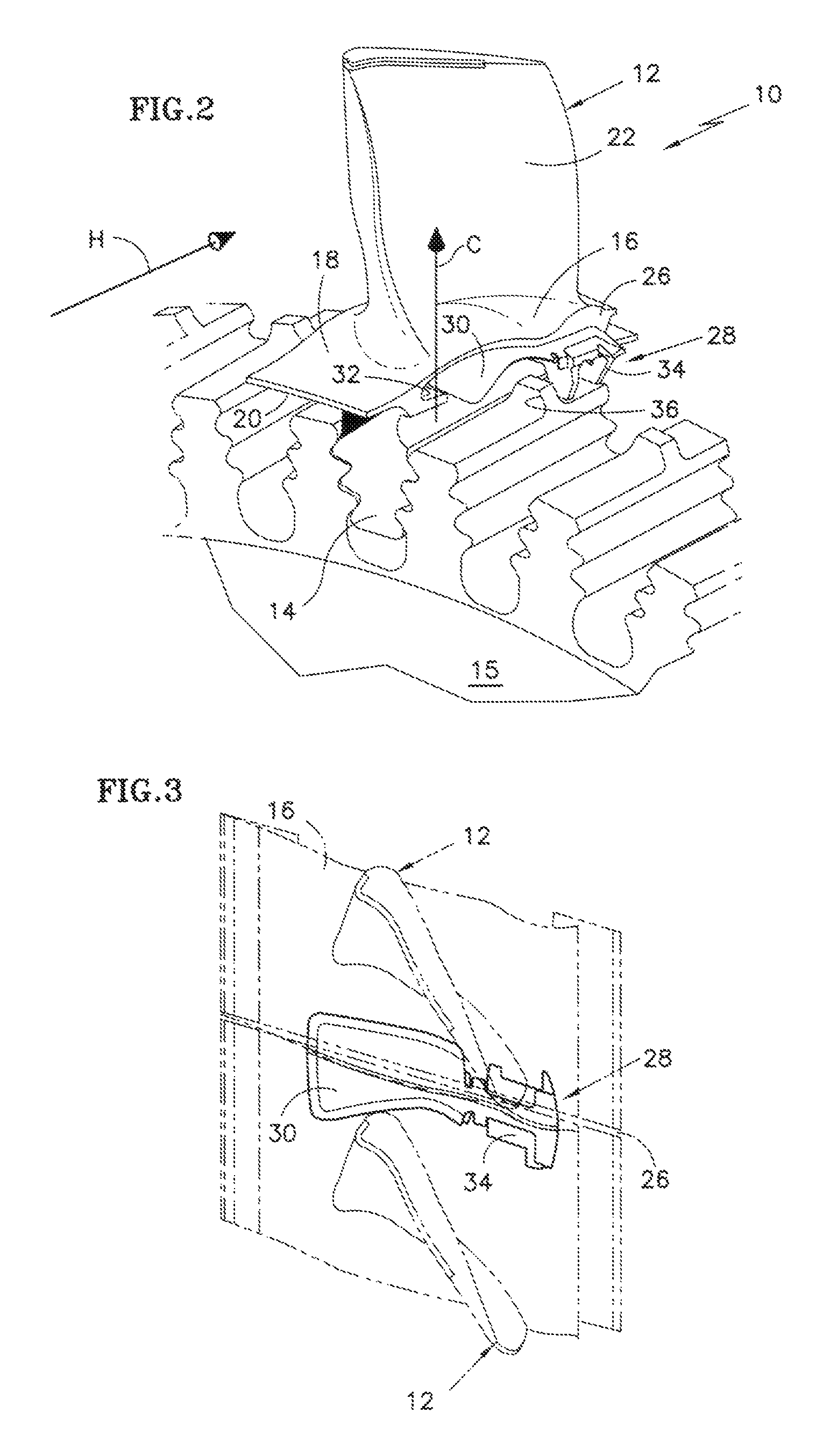
[0008]The damper-seal assembly is centrifugally swung outward to seat against the blade under-platform surfaces when the engine begins to spin such that both the seal and damper remain positively seated throughout engine operation. The seal contacts the inner surfaces of the blade platforms and prevents hot core gas from entering the cavity between adjacent blades while minimizing the leakage of performance penalizing high pressure air into the hot flow path. The seal traverses the seal slot in the damper and seals the gap between adjacent blade platforms for the full axial length of the neck cavity between adjacent blades. The seal also includes a lengthwise seam that aligns with the intersection of the under-platform surfaces of the two adjacent blades along the circumferential gap between the blade platforms.
[0009]The damper provides a stiff bridge between adjacent blade platforms to cause damping. The damper is located in an axially aft most position of the blade platform and includes rear surfaces that form a seal between the adjacent surfaces of the blades to facilitate vibration-dampening performance. A lengthwise seal slot receives the seal when assembled, while an aft leg defines the rear surfaces that provide sealing between adjacent blade platform rear gussets that is conventionally either not sealed or requires a separate sheet-metal seal.
[0010]Accordingly, the damper-seal assembly of this invention achieves an effective seal of gaps between adjacent blade platforms, and dampening of blade platforms when fully assembled in a turbine disk

Problems solved by technology

Hot gases flowing over the platform are prevented from leaking between adjacent turbine blades by a seal as components below the platform are generally not designed to operate for extended durations at the elevated temperatures of the hot gases.

Method used


Image

  • Turbine blade nested seal and damper assembly
  • Turbine blade nested seal and damper assembly
  • Turbine blade nested seal and damper assembly

Examples


Embodiment Construction

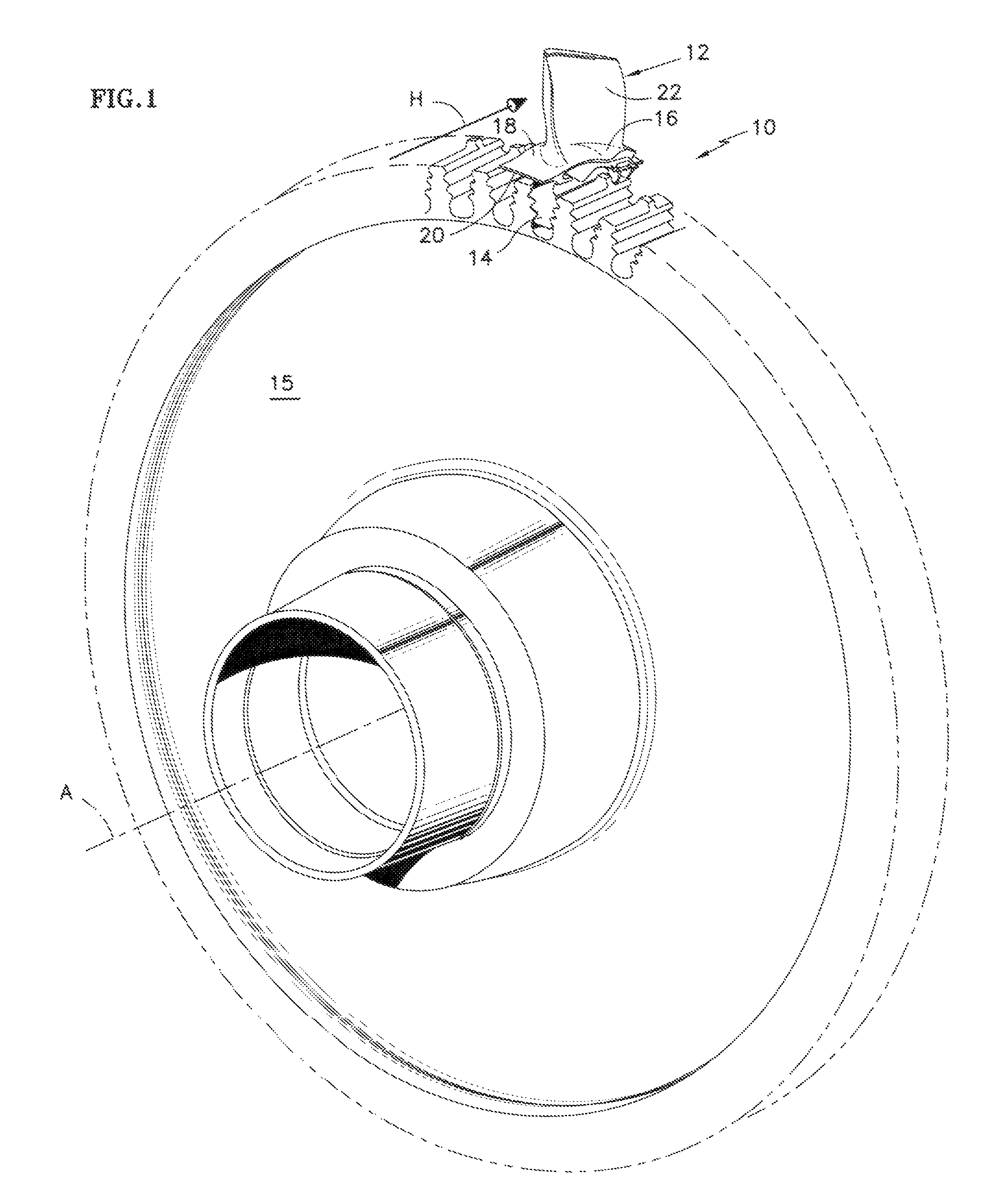
[0022]Referring to FIG. 1, a turbine rotor assembly 10 includes a plurality of adjacent turbine blades 12 (one shown) mounted to a turbine rotor disk 15 about an engine axis A. Each of the turbine blades 12 includes a root 14 that is fit into a corresponding slot of the turbine rotor disk 15. Radially outward of the root 14 is a platform 16. The platform 16 defines an outer platform surface 18 and an inner platform surface 20. The inner surface 20 is disposed radially inward of the outer surface 18. An airfoil 22 extends outward from the platform 16.

[0023]Referring to FIG. 2, hot gas H flows around the airfoil 22 and over the outer platform surface 18 while relatively cooler high pressure air (C) pressurizes the cavity under the platform 16. A gap 26 extends axially between adjacent turbine blades 12 (FIG. 3). The gap 26 prevents contact and allows for thermal growth between adjacent turbine blades 12. A damper-seal assembly 28 includes a seal 30 and a damper 34 to prevent hot gases...


PUM


Abstract

A turbine blade damper-seal assembly includes a seal nested within a damper such that both the seal and damper are disposed to provide sealing between adjacent blade platforms. The seal traverses the seal slot in the damper and seals the gap between adjacent blade platforms for the full axial length of the neck cavity between adjacent blades. The damper is located in an aft most position and includes features to facilitate vibration-dampening performance. The damper also includes features that cause entrapment between blades and therefore avoids the conventionally required protrusions on the blade to retain it in the assembled position.

Description

BACKGROUND OF THE INVENTION[0001]This application relates generally to a turbine blade damper-seal assembly.[0002]Conventional gas turbine engines include a turbine assembly that has a plurality of turbine blades attached about a circumference of a turbine rotor. Each of the turbine blades is spaced a distance apart from adjacent turbine blades to accommodate movement and expansion during operation. Each blade includes a root that attaches to the rotor, a platform, and an airfoil that extends radially outwardly from the platform.[0003]Hot gases flowing over the platform are prevented from leaking between adjacent turbine blades by a seal as components below the platform are generally not designed to operate for extended durations at the elevated temperatures of the hot gases. The seal is typically a metal sheet nested between adjacent turbine blades on an inner surface of the platform. The seal is flexible so as to conform to the inner surface of the platform and prevent the intrusi...

Claims


Application Information

Patent Timeline
Patent Type & Authority Patents(United States)
IPC IPC(8): F01D5/26F01D25/04
CPCF01D5/22F01D5/3007F01D11/006F05D2260/96
Inventor RAMLOGAN, AMARNATHAGRAWAL, RAJENDRA K.DOLL, STEPHEN D.
Owner RTX CORP
Learn More