
Exhalation valve for use in a breathing device

a breathing device and exhalation valve technology, applied in the direction of valve operating means/releasing devices, valve types, functional valve types, etc., can solve the problem of reducing the overall work of underwater breathing

Inactive Publication Date: 2011-09-06
JOHNSON MARK
View PDF127 Cites 17 Cited by
  • Summary
  • Abstract
  • Description
  • Claims
  • Application Information

AI Technical Summary

Benefits of technology

[0009]A need therefore exists for an underwater breathing device that eliminates or reduces some or all of the above-described problems.
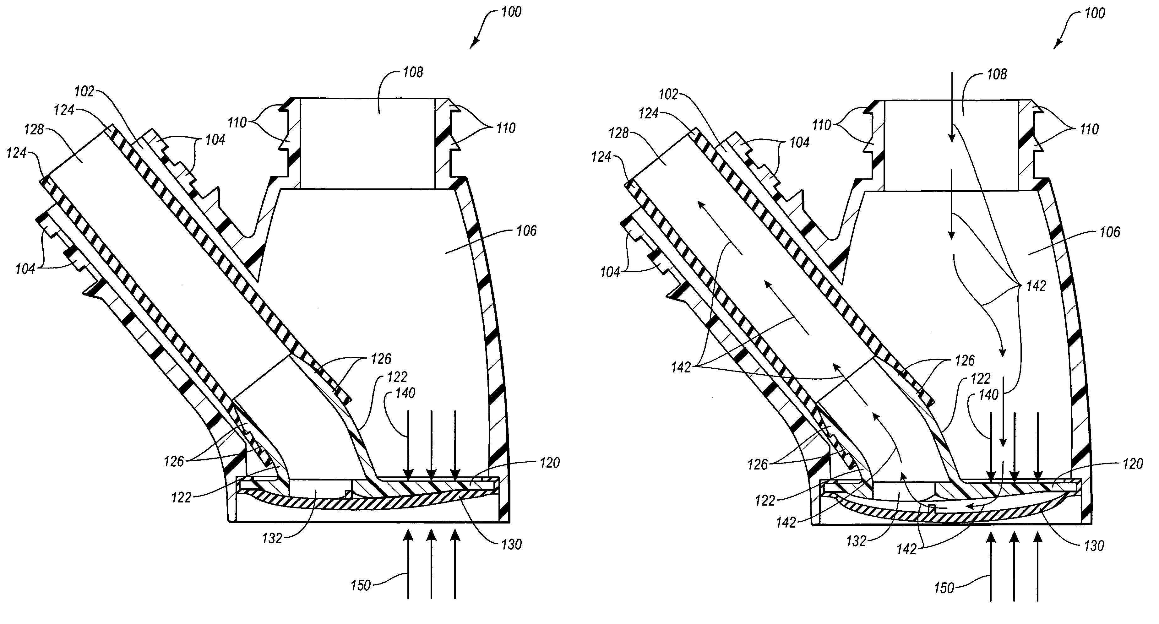
[0010]One aspect is an exhalation valve that may be used in an underwater breathing device. The exhalation valve is potentially configured to produce positive end-expiratory pressure in the airway of a user of the underwater breathing device in order to reduce the overall work of underwater breathing. The exhalation valve may include a plate defining at least one chamber port and an exhalation port. The at least one chamber port may be positioned opposite the exhalation port. The exhalation valve may also include a flexible membrane that is sealable against a surface of the plate and is sized and positioned to be capable of sealing the exhalation port. The flexible membrane may be configured to have a sealed position in which the flexible membrane seals the exhalation port such that substantially no air can flow between the at least one chamber port and the exhalation port. The flexible membrane may also be configured to have an unsealed position in which the flexible membrane does not seal the exhalation port such that air can flow between the at least one chamber port and the exhalation port.
[0012]Yet another aspect is an underwater breathing device that may be configured to produce positive end-expiratory pressure in the airway of a user of the underwater breathing device. The production of positive end-expiratory pressure in the airway of a user of the underwater breathing device may reduce the overall work of underwater breathing. The underwater breathing device may include a chamber and a valve. The chamber may include first and second openings. The chamber may be configured such that when air is being exhaled through the first opening into the chamber in a manner that restricts air from simultaneously escaping through the first opening, there is no unrestricted passageway out of the chamber through which air can exit the underwater breathing device and, as a result, the exhaled air creates an exhalation pressure within the chamber. The valve may restrict airflow between the chamber and the second opening. The valve may include a plate and a flexible membrane. The plate may define the at least one chamber port and the exhalation port. The at least one chamber port may be positioned opposite the exhalation port. The second opening may include the at least one chamber port and the exhalation port. The flexible membrane may be sealable against a surface of the plate and may be sized and positioned to be capable of sealing the exhalation port. The flexible membrane may be configured such that an opening force, comprising any exhalation pressure within the chamber, biases the valve in a first direction and a closing force biases the valve in a second direction, the first direction being substantially opposite the second direction. The flexible membrane may have a closed position in which the flexible membrane seals the exhalation port such that substantially no air is released from the chamber through the exhalation port. The flexible membrane may be disposed in the closed position when the opening force is less than or equal to the closing force. The flexible membrane may also have an open position in which the flexible membrane does not seal the exhalation port such that air is released from the chamber through the exhalation port. The flexible membrane may be disposed in the open position when the opening force exceeds the closing force.
[0014]Yet another aspect is an underwater breathing device configured to produce positive end-expiratory pressure in the airway of a user of the underwater breathing device. The positive end-expiratory pressure in the airway of the user may reduce the overall work of underwater breathing. The underwater breathing device may include a chamber and a valve. The chamber may include first and second openings. The chamber is preferably configured such that when air is being exhaled through the first opening into the chamber in a manner that restricts air from simultaneously escaping through the first opening, there is no unrestricted passageway out of the chamber through which air can exit the underwater breathing device and, as a result, the exhaled air creates an exhalation pressure within the chamber. The valve may function to restrict airflow between the chamber and the second opening. The valve may be configured such that any exhalation pressure within the chamber biases the valve in a first direction and a counter pressure biases the valve in a second direction. The first direction may be substantially opposite the second direction. The valve may have a closed position in which substantially no air is released from the chamber through the second opening. The valve can be disposed in the closed position when any exhalation pressure within the chamber is less than or equal to the counter pressure. The valve may also have an open position in which at least some air is released from the chamber through the second opening. The valve can be disposed in the open position when any exhalation pressure within the chamber exceeds the counter pressure.

Problems solved by technology

The production of positive end-expiratory pressure in the airway of a user of the underwater breathing device may reduce the overall work of underwater breathing.

Method used


Image

  • Exhalation valve for use in a breathing device
  • Exhalation valve for use in a breathing device
  • Exhalation valve for use in a breathing device

Examples


Embodiment Construction

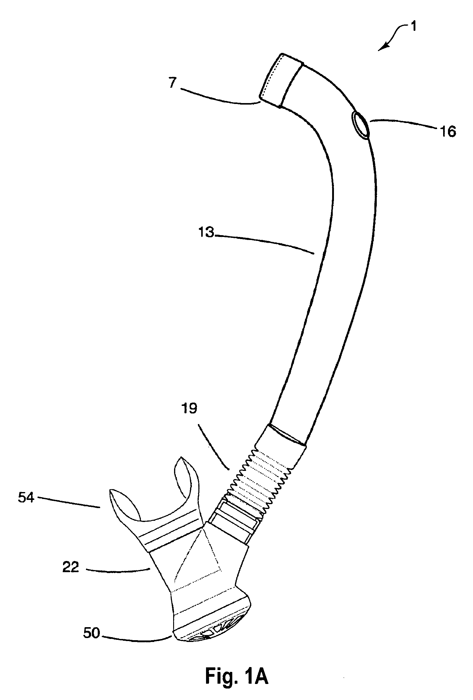
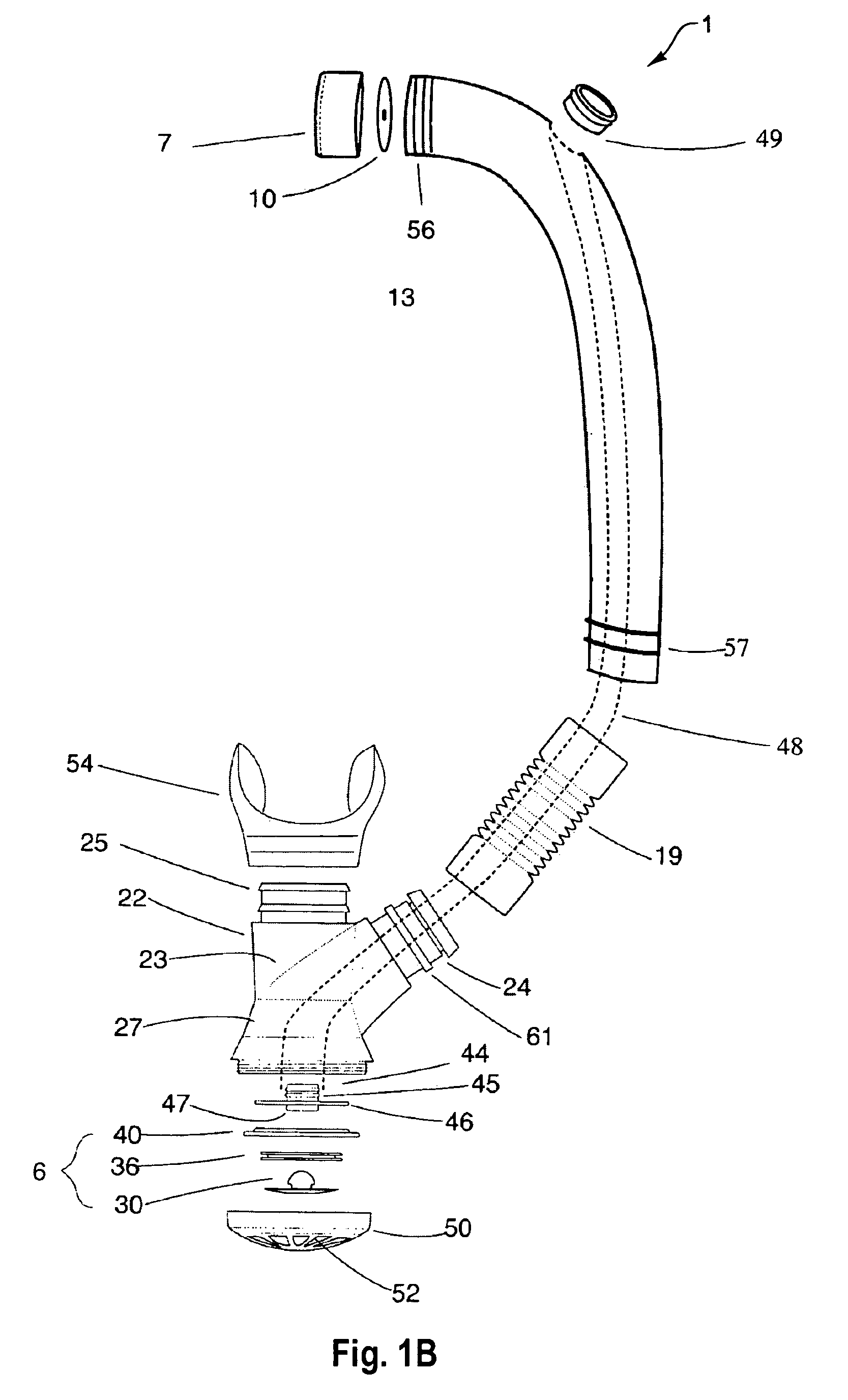
[0056]This invention is generally directed towards an exhalation valve for use in an underwater breathing device. The exhalation valve that is configured to produce positive end-expiratory pressure in the airway of a user of the underwater breathing device. The principles of the present invention, however, are not limited to underwater breathing devices. It will be understood that, in light of the present disclosure, the structures disclosed herein can be successfully used in connection with any device that is intended to produce positive end-expiratory pressure in the airway of a user.

[0057]Additionally, to assist in the description of the exhalation valve, words such as top, bottom, front, rear, right, left and side are used to describe the accompanying figures, which are not necessarily drawn to scale. It will be appreciated, however, that the present invention can be located in a variety of desired positions within an underwater breathing device or other device—including various...


PUM


Abstract

An underwater breathing device, such as a snorkel, may include an exhalation valve. The exhalation valve is configured to produce positive end-expiratory pressure in the airway of a user of the underwater breathing device in order to reduce the overall work of underwater breathing. The exhalation valve includes a plate defining an exhalation port. The exhalation valve also includes a flexible membrane that is sealable against a surface of the plate and is sized and positioned to be capable of sealing the exhalation port. The flexible membrane is configured to have a sealed position in which the flexible membrane seals the exhalation port such that substantially no exhaled air escapes the snorkel. The flexible membrane is also configured to have an unsealed position in which exhaled air escapes the snorkel.

Description

CROSS REFERENCE TO RELATED APPLICATIONS[0001]This application is a continuation-in-part of U.S. patent application Ser. No. 10 / 453,462, entitled “Underwater Breathing Devices And Methods,” filed on Jun. 3, 2003, now U.S. Pat. No. 7,793,656 which claims priority to and the benefit of U.S. provisional patent application Ser. No. 60 / 385,327, filed Jun. 3, 2002. This application also claims priority to and the benefit of U.S. provisional patent application Ser. No. 60 / 683,477, entitled “Valves, Baffles, Shortened Snorkels, Stealth Snorkels, Snorkel Equipment Combined with Scuba Equipment,” which was filed on May 21, 2005. This application also claims priority to and the benefit of U.S. provisional patent application Ser. No. 60 / 728,193, entitled “Snorkel Valve,” which was filed on Oct. 19, 2005. Each of these applications is hereby expressly incorporated by reference herein in its entirety.BACKGROUND OF INVENTION[0002]1. Field of Invention[0003]The present invention relates generally to...

Claims


Application Information

Patent Timeline
Patent Type & Authority Patents(United States)
IPC IPC(8): B63C11/02B63C11/10F16K31/12F16K15/00B63C11/16F16K15/14
CPCA62B9/02B63C11/205Y10T137/7836Y10T137/789Y10T137/784
Inventor JOHNSON, MARK
Owner JOHNSON MARK
Learn More