Brake apparatus

a technology of brake apparatus and servo device, which is applied in the direction of rotary clutches, braking components, control mechanisms, etc., can solve the problems of increasing the number of components and not only the space for accommodating the servo device, so as to reduce the operating force and the operation feeling of the operation member

Inactive Publication Date: 2011-08-30
HONDA MOTOR CO LTD
View PDF14 Cites 12 Cited by
  • Summary
  • Abstract
  • Description
  • Claims
  • Application Information

AI Technical Summary

Benefits of technology

In view of the foregoing prior art problems, it is an object of the present invention to provide an improved brake apparatus which can secure a good operational feeling of an operation member in an initial brake pedal operation region of the operation member by permitting reduction of an operating force to be applied to the operation member.
By increasing, via the transmission unit, the ratio (e.g., lever ratio) between the output amount of the output member and the operation amount of the operation member, it is possible to secure a great output (operating force) of the output member (e.g., push rod) for a given operating force applied to (or caused to act on) the operation member.
Among various known brake apparatus are ones where a negative-pressure servo device is provided between the transmission unit and the master cylinder. The negative-pressure servo device is capable of increasing the operating force by pressing an operating rod of the transmission unit to cancel the negative pressure to thereby allow a spring force to act on the negative-pressure. The negative-pressure servo device, employed in such known brake apparatus, includes an annular (ring-shaped) seal member provided on the operating rod of the transmission unit, to secure a sufficient air pressure. The air pressure produced in the negative-pressure servo device is smaller than a brake fluid pressure produced in a brake circuit of the apparatus. Therefore, sliding resistance of the seal member, produced as the operating rod of the transmission unit is operated, is relatively small. Further, the negative-pressure servo device includes a reaction force rubber member provided between the transmission unit and the master cylinder. By such small sliding force of the seal member and by the provision of the reaction force rubber member, the brake apparatus provided with the negative-pressure servo device can secure a good initial operating force of the operation member. However, the provision of the negative-pressure servo device requires not only a space for accommodating the servo device but also an increased number of component parts.
To avoid the aforementioned inconveniences, the transmission unit employed in the present invention is connected directly to the master cylinder without a negative-pressure servo device being provided between the transmission unit and the master cylinder. Thus, the present invention can eliminate the need for the accommodating the servo device and can reduce the number of component parts.
In an embodiment of the present invention, the transmission unit includes a pivot link connected via the output member to the master cylinder, and a connection link interconnecting the pivot link and the operation member. The connection link is arranged to be pulled away from the pivot link by the operation member as the operation member is operated in a non-operating position thereof Because the connection link is arranged to be pulled (rather than being pressed or pushed) by the operation member as the operation member is operated, it is possible to prevent the connection link from interfering with the operation member etc. Thus, in a latter-half operation amount region of the operation member, the lever ratio can be increased as the operation amount of the operation member increases. As a consequence, in case of a failure of a main power supply, for example, it is possible to increase the output (operating force) of the output member with respect to the operating force applied to the operation member. Thus, the present invention can increase the fluid pressure of the master cylinder and allows the brake cylinder to operate with the thus-increased fluid pressure.

Problems solved by technology

However, the provision of the negative-pressure servo device requires not only a space for accommodating the servo device but also an increased number of component parts.

Method used


Image

  • Brake apparatus
  • Brake apparatus
  • Brake apparatus

Examples


first embodiment

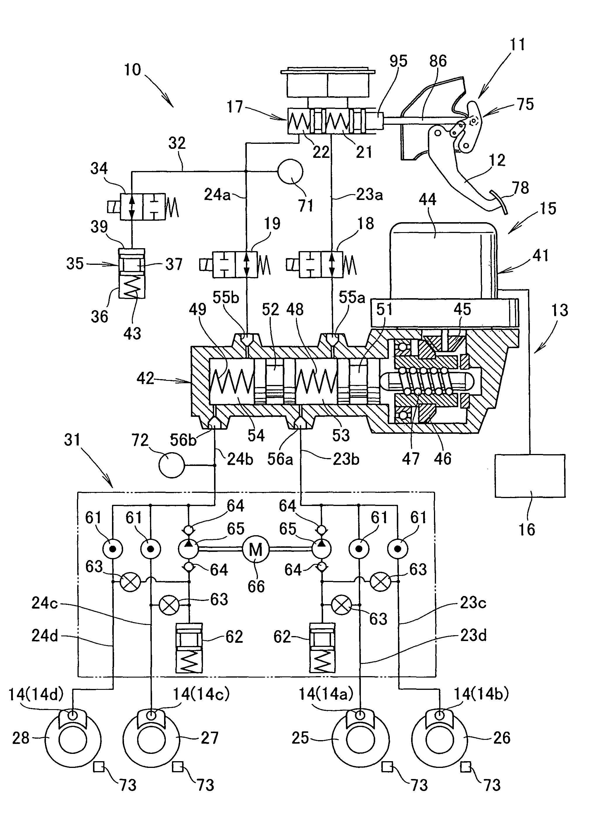
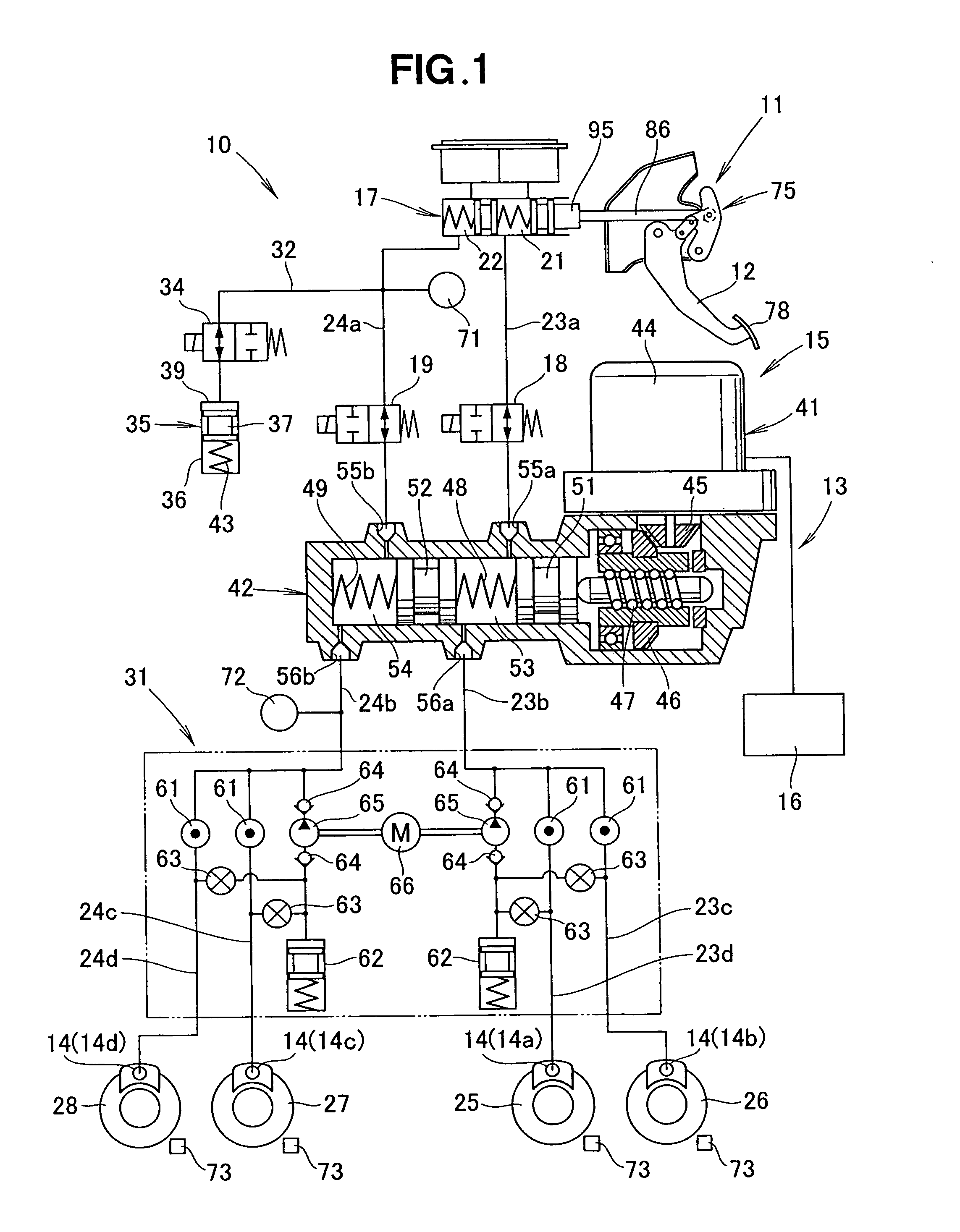
Reference is now made to FIG. 1 diagrammatically showing a fluid pressure circuit of a brake apparatus of the present invention. The brake apparatus 10 includes: a brake pedal device 11 having an operation member in the form of a pendant-type brake pedal 12 incorporated therein, a plurality of brake cylinders 14 for applying a braking force to road wheels of a vehicle; an electric braking-force control device 13 capable of electrically controlling the braking force in accordance with an operation amount or leg power (operating force) of the brake pedal 12; a master cylinder 17 for producing a fluid pressure in response to operation of the brake pedal 12; an operation amount simulator for storing a brake fluid supplied form the master cylinder 17; and a pair of block valves (block members) 18 and 19 for blocking communication of the brake fluid between the master cylinder 17 and the brake cylinders 14. The electric braking-force control device 13 includes an electric braking-force pr...

second embodiment

FIG. 7 is a diagram showing a fluid pressure circuit of the brake apparatus 140 of the present invention. The brake apparatus 40 includes: the brake pedal device 11 having the brake pedal 12 incorporated therein, the brake cylinders 14 for applying a braking force to the wheels of the vehicle; an electric braking-force control device 141 capable of electrically controlling the braking force in accordance with an operation amount or leg power (operating force) of the brake pedal 12; the master cylinder 17 for producing a pressure of a brake fluid in response to operation of the brake pedal 12; the operation amount simulator 35 for storing a brake fluid supplied form the master cylinder 17; and the block valves (block members) 18 and 19 for blocking communication of the brake fluid between the master cylinder 17 and the brake cylinders 14.

The electric braking-force control device 14 includes an electric braking-force production section 142 for producing a braking force in response to ...


PUM


Abstract

Brake apparatus includes a transmission unit for operatively connecting a brake pedal to a master cylinder, and the transmission unit is a mechanism capable of varying a ratio between an output amount of a push rod connected to a master cylinder and an operation amount of the brake pedal. Further, the transmission unit is constructed in such a manner that, in an initial operation region of the brake pedal, a ratio of the operation amount of the brake pedal to the output amount of the push rod is set to be greater than in another operation region immediately following the initial operation region.

Description

FIELD OF THE INVENTIONThe present invention relates to a vehicular brake apparatus including a simulator storing a brake fluid, supplied from a master cylinder, and a transmission unit interconnecting an operation member and the master cylinder.BACKGROUND OF THE INVENTIONAmong the conventionally-known vehicular braking apparatus are ones provided with a simulator (i.e., operation amount simulator) for securing good operating characteristics of a brake pedal. Such braking apparatus are known, for example, from Japanese Patent No. 3489453 (hereinafter referred to as “Patent Literature 1”) and constructed in such a manner that a tread force or leg power is applied to (or caused to act on) a brake pedal, used as an operation member, so as to press a piston of a master cylinder and that a spring within the master cylinder is compressed by a fluid pressure produced within the master cylinder. With the spring within the master cylinder thus compressed, a reactive force acting on the brake ...

Claims


Application Information

Patent Timeline
Patent Type & Authority Patents(United States)
IPC IPC(8): G06F7/00
CPCB60T7/06B60T8/4081B60T8/409B60T11/18G05G1/46G05G7/04B60T13/745Y10T74/18992Y10S303/90
Inventor TOYOHIRA, TOMOYAINOUE, ARATAAKUTSU, KAZUYOSHIHATANO, KUNIMICHI
Owner HONDA MOTOR CO LTD
Why Eureka
Try Eureka