X-ray imaging apparatus, X-ray imaging method, and X-ray imaging program
a technology of x-ray imaging and x-ray imaging method, which is applied in the direction of material analysis using wave/particle radiation, optical radiation measurement, instruments, etc., can solve the problems of difficult image of living soft tissues made of carbon, hydrogen, oxygen, etc., and not desirable for medical us
- Summary
- Abstract
- Description
- Claims
- Application Information
AI Technical Summary
Benefits of technology
Problems solved by technology
Method used
Image
Examples
first embodiment
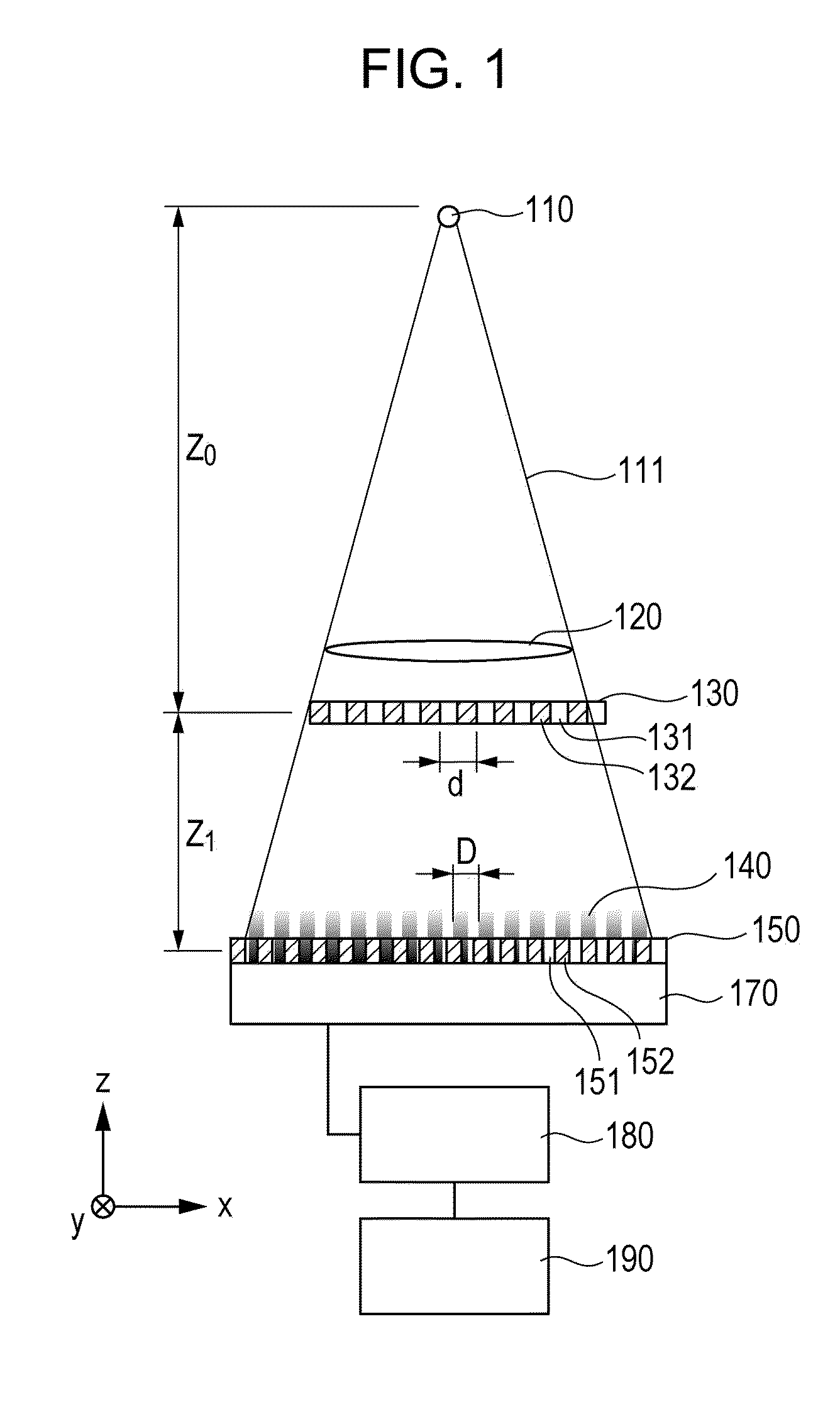
[0024]FIG. 1 illustrates an exemplary configuration of an X-ray imaging apparatus using Talbot interference. A process to acquire a phase image by using the X-ray imaging apparatus will be described in detail.
(X-Ray Source)
[0025]X-rays 111 generated by an X-ray source 110 are transmitted through a subject 120. When the X-rays 111 are transmitted through the subject 120, the phase of the X-rays 111 is changed and the X-rays 111 is absorbed depending on the composition, shape, etc., of the subject 120.
[0026]The X-rays may be continuous X-rays or characteristic X-rays. The wavelength of the X-rays is selected in a range from about 0.1 Å to 5 Å. A wavelength selection filter and / or a grating for a source may be provided downstream of the X-ray source 110.
[0027]The X-rays 111 transmitted through the subject 120 is transmitted through a phase grating 130. Then, the x-rays 111 form an interference intensity distribution 140 by the Talbot effect.
[0028]The phase grating 130 is...
second embodiment
[0093]An X-ray imaging apparatus according to a second embodiment of the present invention will be described with reference to FIGS. 7A and 7B. In this embodiment, a spatial resolution is increased rather than the spatial frequency spectrum described in the first embodiment and shown in FIG. 5C.
[0094]FIG. 7B illustrates a spatial frequency spectrum which is described in this embodiment. To acquire such a frequency spectrum, a fundamental period of a two-dimensional Moiré resulted from an interference intensity distribution and an absorption grating is determined with respect to a pixel period of the X-ray detector to achieve the following ratio.
2√{square root over (2)} times
[0095]Also, the orientation of the Moiré is adjusted to be inclined at 45 degrees to the pixel array.
[0096]FIG. 7A illustrates the intensity distribution of the Moiré on the X-ray detector in this state. Reference sign 710 denotes a light-receiving surface of the X-ray detector, 720 denotes bright sections of the...
third embodiment
[0110]An X-ray imaging apparatus according to a third embodiment of the present invention will be described with reference to FIGS. 8A and 8B. In this embodiment, the spatial resolution is increased rather than the spatial frequency spectrum described in the first embodiment and shown in FIG. 5D.
[0111]FIG. 8B illustrates a spatial frequency spectrum which is described in this embodiment. To acquire such a frequency spectrum, a fundamental period of a two-dimensional Moiré resulted from an interference intensity distribution and an absorption grating is determined to be three times a pixel period of the X-ray detector, and the orientation of the Moiré is aligned with the pixel array.
[0112]FIG. 8A illustrates the intensity distribution of the Moiré on the X-ray detector in this state. Reference sign 810 denotes a light-receiving surface of the X-ray detector, 820 denotes bright sections of the Moiré, d denotes a period of the Moiré, and P denotes a pixel period of the X-ray detector. ...
PUM
 Abstract
Description
Claims
Application Information
 - R&D
- Intellectual Property
- Life Sciences
- Materials
- Tech Scout
- Unparalleled Data Quality
- Higher Quality Content
- 60% Fewer Hallucinations
Browse by: Latest US Patents, China's latest patents, Technical Efficacy Thesaurus, Application Domain, Technology Topic, Popular Technical Reports.
© 2025 PatSnap. All rights reserved.Legal|Privacy policy|Modern Slavery Act Transparency Statement|Sitemap|About US| Contact US: help@patsnap.com


