
Method for operating a fuel system

a fuel system and fuel rail technology, applied in the direction of electrical control, process and machine control, instruments, etc., can solve the problem of deviating pressure in the fuel rail

Inactive Publication Date: 2011-08-02
ROBERT BOSCH GMBH
View PDF4 Cites 13 Cited by
  • Summary
  • Abstract
  • Description
  • Claims
  • Application Information

AI Technical Summary

Benefits of technology

The present invention provides a method for detecting malfunctions of pressure sensors in fuel systems using the nonlinear characteristic of the activation period of the fuel injection device. This method allows for the detection of malfunctions without the need for additional components and improves the accuracy and reliability of the fuel system. The method uses the difference in the time required for a pressure sensor to reach its maximum activation during a fuel injection to detect any deviation in the actual pressure in the fuel rail. This deviation indicates a malfunction of the pressure sensor. The method may be carried out during normal engine operation or during a repair shop examination. The technical effects of the present invention include improved fuel system durability, reduced fuel consumption, improved emissions control, and the elimination of manipulation liability problems.

Problems solved by technology

If the pressure sensor is operating incorrectly or is intentionally manipulated, the real prevailing pressure in the fuel rail deviates from the pressure ascertained from the signal of the pressure sensor.

Method used


Image

  • Method for operating a fuel system
  • Method for operating a fuel system
  • Method for operating a fuel system

Examples


Embodiment Construction

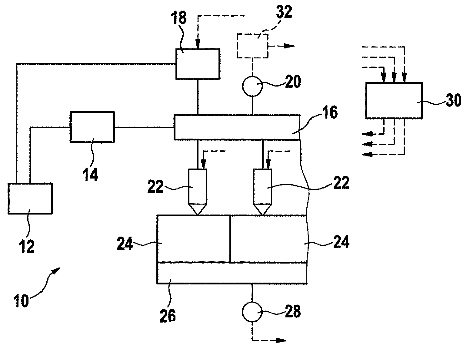
[0017]A fuel system bears reference numeral 10 as a whole in FIG. 1. It includes a fuel container 12, from which a pumping unit 14, for example, including a predelivery pump and a high-pressure pump, delivers the fuel into a fuel rail 16. A pressure regulating valve 18 and a pressure sensor 20 are connected thereto.

[0018]Furthermore, multiple injectors 22 are connected to fuel rail 16, which inject the fuel directly into combustion chambers 24 of an internal combustion engine (not shown further) assigned thereto. Upon the combustion of the injected fuel in combustion chambers 24, a crankshaft 26 is set into rotation. A crankshaft sensor 28 detects the rotations and the speed of crankshaft 26.

[0019]The operation of the internal combustion engine and also of fuel system 10 is controlled and / or regulated by a control and regulating device 30. For this purpose, control and regulating device 30 receives, inter alia, a signal from pressure sensor 20 and from crankshaft sensor 28. Inter al...


PUM


Abstract

In a fuel system of an internal combustion engine, the fuel quantity injected into a combustion chamber is a function of an activation period, during which a fuel injection device is activated. A pressure sensor detects the pressure in the fuel rail and provides a signal. The pressure in the fuel rail may be regulated to a setpoint pressure using a setting unit and employing the signal provided by the pressure sensor. The following method is provided for testing the fuel system:(a) establishing a test fuel quantity to be injected;(b) operating the internal combustion engine using a first setpoint pressure and a first activation period corresponding thereto and to the test fuel quantity to be injected;(c) detecting a speed- or torque-dependent variable characterizing the operating state;(d) operating the internal combustion engine using a second setpoint pressure and a second activation period corresponding thereto and to the test fuel quantity to be injected;(e) detecting a speed- or torque-dependent variable characterizing the operating state;(f) implementing an action if the variables detected in (c) and (e) differ by more than a limit value.

Description

BACKGROUND INFORMATION[0001]Common rail fuel systems in which the fuel is delivered into a fuel rail by a pumping unit are known from the market. Multiple fuel injection devices are connected thereto, which inject the fuel directly into combustion chambers assigned thereto. The pressure in the fuel rail is detected by a pressure sensor and regulated to a variable setpoint pressure by a setting unit. The fuel quantity injected into a combustion chamber is a function on the one hand of the instantaneous actual pressure in the fuel rail and on the other hand, of the activation period and the injection period of the fuel injection devices related thereto.[0002]The signal provided by the pressure sensor may be flawed due to damage, intentional manipulation, or pronounced drift, which has the result that the real pressure prevailing in the fuel rail deviates from the setpoint pressure more than desired. The durability of components of the fuel system may thus be reduced, the mixture forma...

Claims


Application Information

Patent Timeline
Patent Type & Authority Patents(United States)
IPC IPC(8): G06F19/00F02M51/00
CPCF02D41/222F02D41/3836F02D2041/223
Inventor OLBRICH, STEPHANPECK, RAINERKRIECHBAUM, CHRISTIANSCHENK, MICHAELMEYER-SALFELD, STEFFENZIEHER, RENEVIERECK, MARKUS
Owner ROBERT BOSCH GMBH
Learn More