Variable reluctance position sensor

a technology of position sensor and resistance, applied in the direction of measurement device, sensor output, instruments, etc., can solve the problems of inability to disclose characteristic, inability to perfect the compensation applied, and the influence of compensation error the smaller the measured inductance, so as to achieve excellent linearity and reduce manufacturing costs

Inactive Publication Date: 2011-08-02
MOVING MAGNET TECH
View PDF17 Cites 5 Cited by
  • Summary
  • Abstract
  • Description
  • Claims
  • Application Information

AI Technical Summary

Benefits of technology

[0018]By virtue of these particular features, the invention therefore makes it possible to manufacture, very simply, both linear and rotary transducers making it possible to have excellent linearity and, for the rotary transducers, maximum travels close to 360° , with a mean or initial induction to be measured close to zero gauss.
[0019]In addition, the device according to the invention has a clearly lower manufacturing cost and a great variety of transducers with different target shapes or geometry, for both linear and rotary transducer applications.

Problems solved by technology

The variation of transducer sensitivity as a function of temperature must be compensated for, but the compensation applied cannot be perfect and the influence of these compensation errors will be smaller the smaller the measured inductance is.
On the other hand, it does not disclose the characteristic according to which the Hall-effect sensor is seated in a cavity of the permanent magnet.
This patent application does not disclose anything at all about a variable-reluctance analog position transducer seeking to create zero gauss.
The technical solutions disclosed in the foregoing patents may be satisfactory in their particular application, but the major drawback of these devices lies in the fact that the function of measurement of angular position by a variation of the magnetic induction has a maximum travel of only ±90° around the zero gauss position.

Method used


Image

  • Variable reluctance position sensor
  • Variable reluctance position sensor
  • Variable reluctance position sensor

Examples


Embodiment Construction

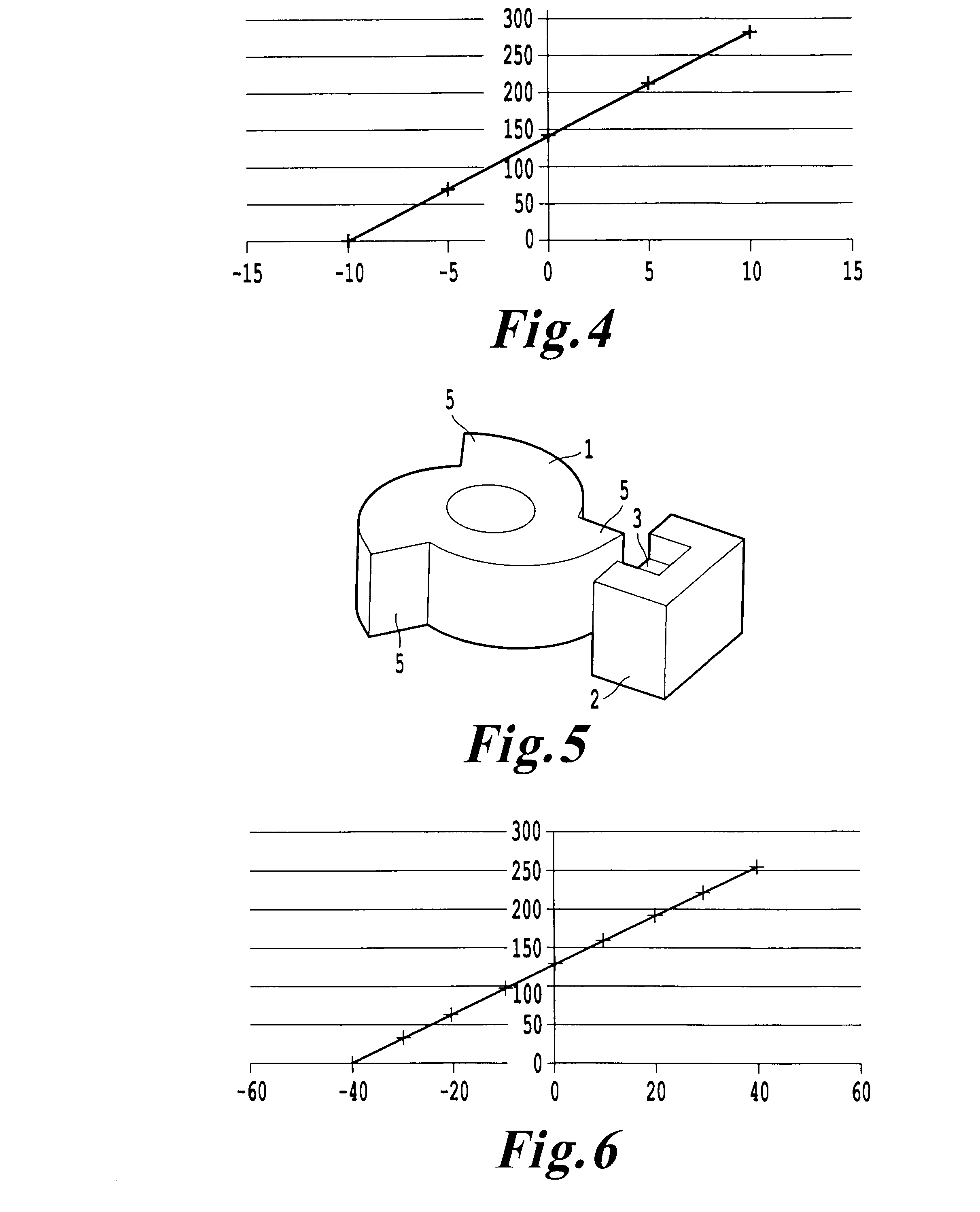
[0060]One of the principles of the invention is to create an analog induction variation of low mean value, such as a few hundred gauss, which consists in a function of the linear or angular position of a ferromagnetic piece and which can be exploited by a magnetosensitive element.

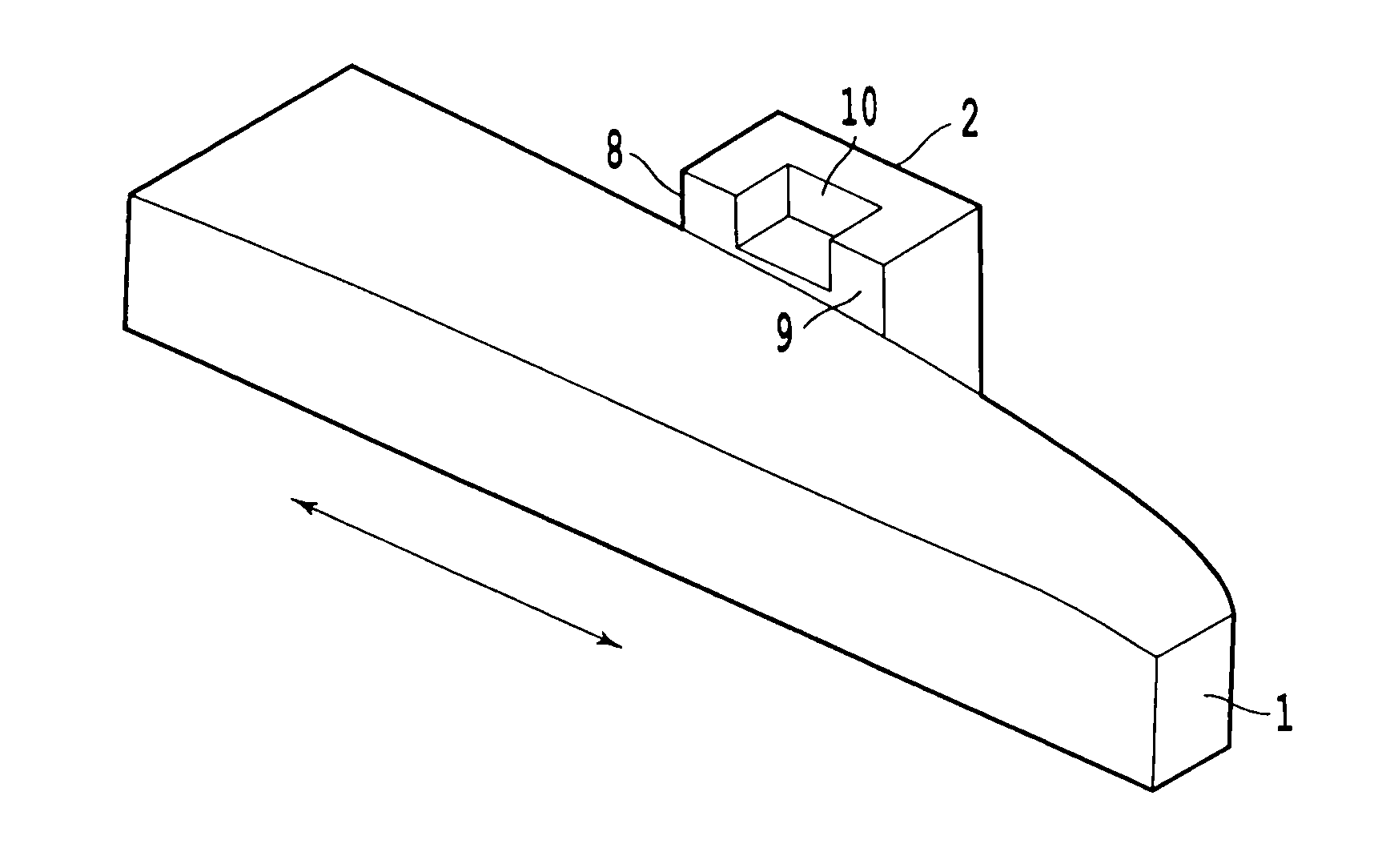
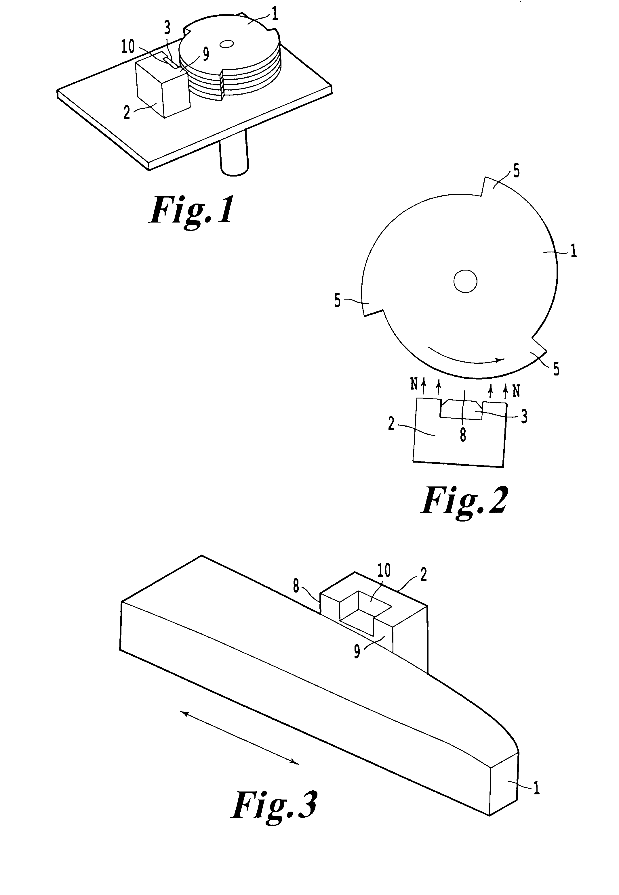
[0061]As is evident in the different figures, the variable-reluctance analog position transducer intended to determine the position of a target 1 includes the said target 1 of ferromagnetic material, having a supposedly infinite permeability, a permanent magnet 2 and an element sensitive to the sense and intensity of a magnetic field, referred to hereinafter as “magnetosensitive element”3, such as a Halleffect sensor, disposed in the air gap formed between magnet 2 and target 1.

[0062]Magnet 2 is a magnet having two poles, one of the poles being directed from the edge of the air gap over the surface of the magnet forming the side of the air gap, the other pole being on the opposite side.

[0063]The magnetizati...


PUM


Abstract

A variable reluctance analog position device designed to determine the position variation of a target made from a ferromagnetic material. The device includes at least one magnet, the target and the magnet defining a gap therebetween. A magnetosensitive element detects induction variation produced in the gap by relative movement of the target relative to the magnet. The magnet is magnetized in a direction essentially perpendicular to the front surface of the magnet, which defines one edge of the gap. The magnet includes a cavity open at the front surface thereof and the magnetosensitive element is housed in the cavity. Moreover, the target is provided with a specific geometric configuration determined such that the induction variation according to the position of the target corresponds to a pre-defined function.

Description

CROSS-REFERENCE TO RELATED APPLICATIONS[0001]This application is a continuation of U.S. application Ser. No. 10 / 530,485, filed on Sep. 27, 2005, the entire content of which is incorporated herein by reference. U.S. application Ser. No. 10 / 530,485 is based upon and claims priority under 35 U.S.C. §371 from International Patent Application No. PCT / FRO3 / 02949, filed Oct. 7, 2003 and claims priority under 35 U.S.C. §119 from French Patent Application No. 02 / 12425, filed Oct. 7, 2002.BACKGROUND OF THE INVENTION[0002]The present invention relates to a variable-reluctance analog position transducer device and method. It is applicable in particular but not exclusively to devices suitable for measuring a variation of air gap between a ferromagnetic target and a transducer, the ferromagnetic target being displaced in linear or rotary manner opposite the transducer.[0003]In general, the invention comprises a contactless rotary or linear transducer making it possible to obtain very linear induc...

Claims


Application Information

Patent Timeline
Patent Type & Authority Patents(United States)
IPC IPC(8): G01B7/14G01B7/30G01D5/14G01D5/16
CPCG01D5/147G01D2205/73G01D2205/772G01D2205/777
Inventor FRACHON, DIDIERGANDEL, PIERRE
Owner MOVING MAGNET TECH
Why Eureka
Try Eureka