Backside-illuminated solid-state image pickup device
a solid-state image and pickup device technology, applied in the direction of radio frequency controlled devices, television system scanning details, etc., can solve the problems of analog circuits that cannot produce stable waveforms, pulse noises are likely to leak in logic circuits, and the back surface of silicon substrates cannot be grounded with the back surface of silicon substrates bonded to a package, etc., to achieve stable waveforms and less nois
- Summary
- Abstract
- Description
- Claims
- Application Information
AI Technical Summary
Benefits of technology
Problems solved by technology
Method used
Image
Examples
first embodiment
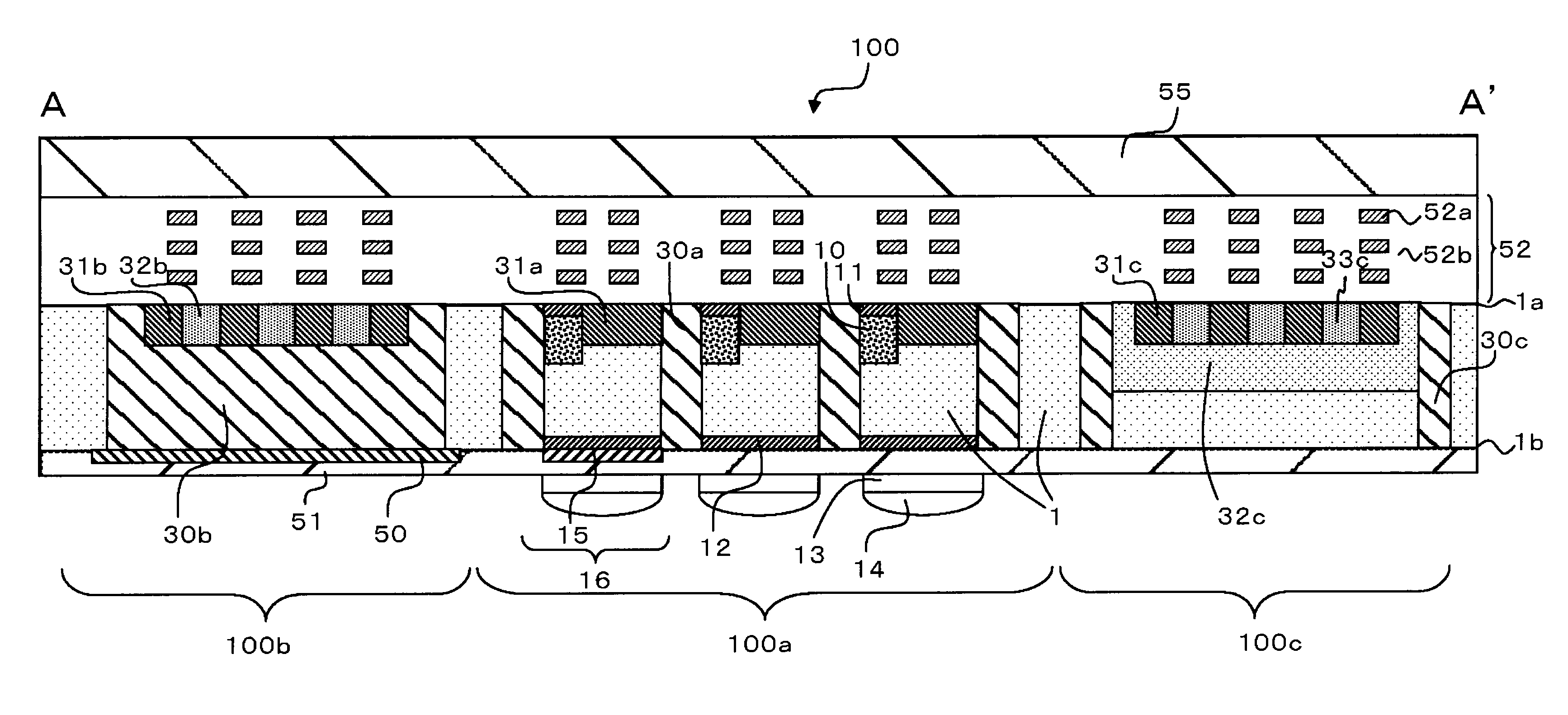
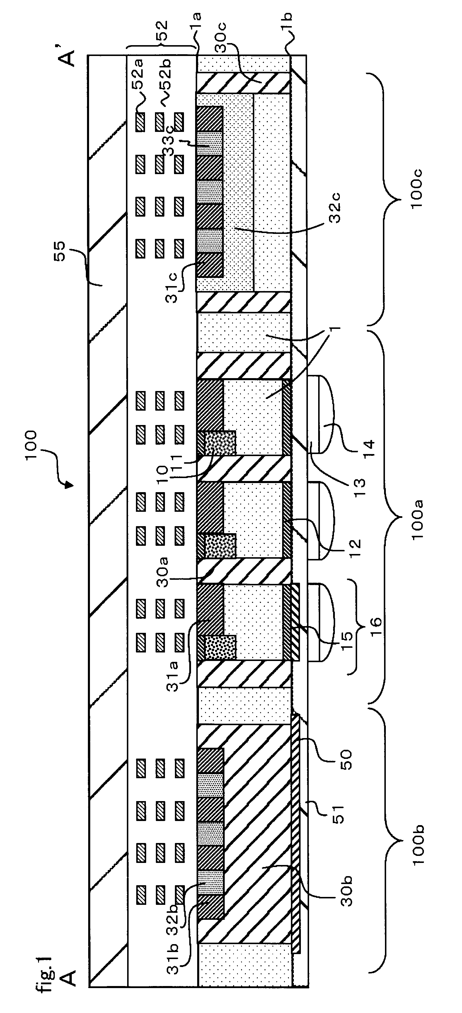
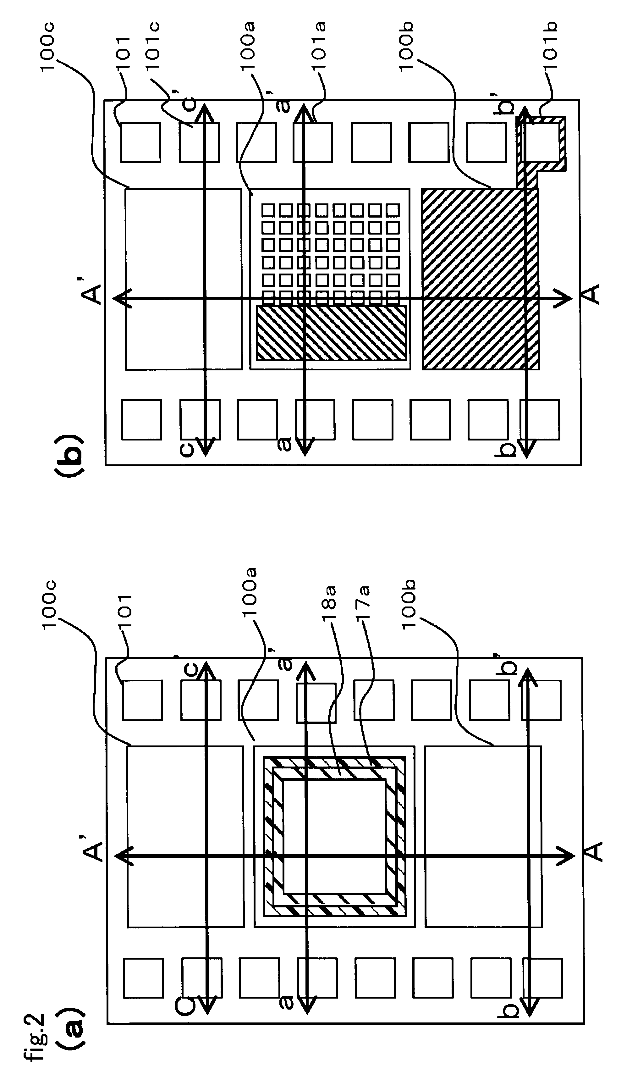
[0031]FIG. 1 is a cross-sectional view of a backside-illuminated solid-state image pickup device 100 according to a first embodiment of the present invention, and FIGS. 2A and 2B are plan views of the backside-illuminated solid-state image pickup device 100 according to the first embodiment of the present invention (in which FIG. 2A shows a front surface side and FIG. 2B shows a back surface side). Note that the cross-sectional view in FIG. 1 is one taken along an A-A′ line in FIG. 2.
[0032]As shown in FIG. 1, the backside-illuminated solid-state image pickup device 100 of this embodiment includes an N type semiconductor layer 1, and this semiconductor layer 1 includes a first principal surface (a front surface) 1a and a second principal surface (a back surface) 1b opposed to this first principal surface 1a. Moreover, this semiconductor layer 1 includes a pixel area 100a, and an analog circuit area 100b as well as a logic circuit area 100c which collectively serve as a peripheral cir...
second embodiment
[0074]FIG. 11 is a cross-sectional view of a backside-illuminated solid-state image pickup device 100 according to a second embodiment of the present invention, and FIGS. 12A and 12B are plan views of the backside-illuminated solid-state image pickup device 100 according to the second embodiment of the present invention (in which FIG. 2A shows a front surface side and FIG. 2B shows a back surface side). Note that the cross-sectional view in FIG. 11 is one taken along an A-A′ line in FIG. 12.
[0075]This embodiment is different from the first embodiment in that the metal layer which is grounded is provided only on the back surface side of the analog circuit area in the first embodiment, whereas metal layers which are grounded are also provided on the back surface side of the pixel area and the logic circuit area in this embodiment.
[0076]To be more precise, as shown in FIG. 11, the backside-illuminated solid-state image pickup device 100 of this embodiment also includes the metal layers...
third embodiment
[0090]FIG. 15A is a cross-sectional view of a backside-illuminated solid-state image pickup device 100 according to a third embodiment of the present invention, and FIG. 15B is a plan view of the backside-illuminated solid-state image pickup device 100 according to the third embodiment of the present invention.
[0091]This embodiment is different from the second embodiment in that a metal layer 50 which is grounded and has a film thickness of 300 to 800 nm is formed on the second principal surface 1b side of the logic circuit area 100c and of the analog circuit area 100b.
[0092]Specifically, the logic circuit area 100c includes the first P type area 30c formed to lie between the first principal surface 1a and the second principal surface 1b, the metal layer 50 formed at least partially on the second principal surface 1b of the first P type area 30c, the second N type area formed in part of the first principal surface 1a side of the first P type area 30c, and the VSS pad 101c electrica...
PUM
 Abstract
Description
Claims
Application Information
 - R&D
- Intellectual Property
- Life Sciences
- Materials
- Tech Scout
- Unparalleled Data Quality
- Higher Quality Content
- 60% Fewer Hallucinations
Browse by: Latest US Patents, China's latest patents, Technical Efficacy Thesaurus, Application Domain, Technology Topic, Popular Technical Reports.
© 2025 PatSnap. All rights reserved.Legal|Privacy policy|Modern Slavery Act Transparency Statement|Sitemap|About US| Contact US: help@patsnap.com


