
Method and system for a wireless multi-hop relay network

Inactive Publication Date: 2011-07-26
APPLE INC
View PDF4 Cites 66 Cited by
  • Summary
  • Abstract
  • Description
  • Claims
  • Application Information

AI Technical Summary

Benefits of technology

[0008]The invention provides several solutions for the current issues in the MMR multi-hop architecture. Radio resource access is accompanied with topology information and shared/dedicated radio resource allocation policy. The overall end-to-end relay control is done in a collaborate manner among BS and RS. To accommodate large scale network size, efficient radio

Problems solved by technology

The MMR architecture presents new complications.
Use of CIDs in MMR networks becomes a critical issue.
As a result, RS MAC PDU decoding consumes excessive resources and RS forwarding tables become very large and ultimately unmanageable.
Furthermore, to execute a handover of an MS from one branch to another branch of the MMR network, all the MS CIDs have to be transferred from all RS along the old branch to all RS along the new branch, resulting in very inefficient MMR relay operation.

Method used


Image

  • Method and system for a wireless multi-hop relay network
  • Method and system for a wireless multi-hop relay network
  • Method and system for a wireless multi-hop relay network

Examples


Embodiment Construction

[0058]A wireless multi-hop relay access network is described herein. In a multi-hop relay access network, relay stations (RS) are introduced for fixed, nomadic and mobile relay usage between base stations (BS) and subscriber stations (SS). The functional scope of a relay station can scale from being very simple such as an analog signal repeater, to a base station compliant fully functional device capable of radio resource scheduling, security authentication and connection management for mobile stations, in case a base station fails.

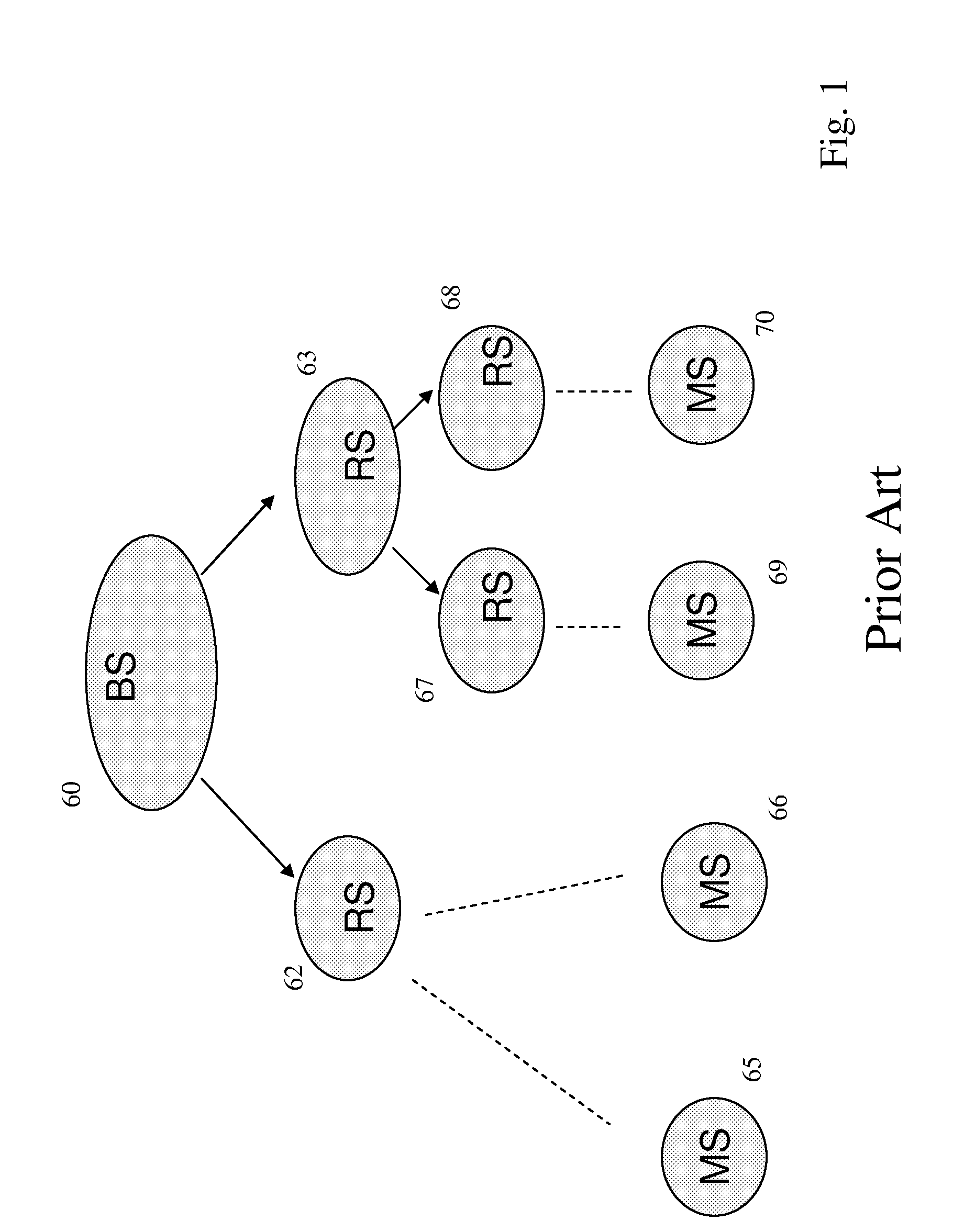
[0059]FIG. 1 is a schematic diagram of a very simple two-tier PMP relay network. In this example, the SS are mobile stations (MS). MS is used for the remainder of this description, as the invention provides advantages when used with mobile stations, though it is understood that mobile stations are a subset of subscriber stations to which the invention broadly applies. At the tree trunk level, BS 60 communicates with RS 62 and RS 63. RS 62 in turn communic...


PUM


Abstract

In a wireless multi-hop relay network arranged in a tree topology, the base station and one or more relay stations are associated as a virtual base station (VBS). The base station and each relay station have a unique virtual base station identifier (VBS-ID) associated with the path defined by the base station and the one or more relay stations. a relay station in the branch uses its VBS-ID for communicating with an attached subscriber station (e.g. a mobile station) such that communications between the base station and subscriber station occur via the VBS. Subscriber station data communications are relayed between the base station and the one or more relay stations over the VBS via a tunnel connection. The VBS is autoconfigurable. Mobility for subscriber stations and relay stations is provided through reconfiguration of VBS's.

Description

RELATED APPLICATIONS[0001]This application claims the benefit of U.S. Provisional Patent Application No. 60 / 776,448 filed on Feb. 4, 2006, which is hereby incorporated by reference in its entirety.[0002]This application is related to commonly owned and co-pending U.S. patent application Ser. No. 11 / 478,719, filed on Jul. 3, 2006, titled “METHOD AND SYSTEM FOR A WIRELESS MULTI-HOP RELAY NETWORK”, which is hereby incorporated by reference in its entirety.FIELD OF THE INVENTION[0003]The invention relates to wireless networking protocols and systems.BACKGROUND OF THE INVENTION[0004]WiMAX, described in the IEEE 802.16 Wireless Metropolitan Area Network (MAN) standard (IEEE 802.16-2005), allows for high-speed wireless data transmissions over long distances. The core components of an 802.16 network are base stations (BS) and subscriber stations (SS). An SS may be a mobile station (MS). The WiMAX network was originally designed as a Point-to-Multipoint (PMP) architecture. The 802.16-2005 st...

Claims


Application Information

Patent Timeline
IPC IPC(8): H04B3/36H04B7/14H04L45/586H04L45/74H04L47/32
CPCH04B7/155H04B7/2606H04L45/54H04W40/22H04W40/24H04L45/586H04W40/12H04W76/12H04B7/15592H04L45/745H04L47/32
Inventor WANG, GUO QIANGTONG, WENWU, SHIQUAN
Owner APPLE INC
Learn More