
Plastic component having visible part and light source

a technology of visible parts and components, applied in dashboard lighting devices, transportation and packaging, lighting and heating equipment, etc., can solve the problems of high use complexity, led service life exceeding the service life of a vehicle,

Inactive Publication Date: 2011-07-26
EMS CHEM AG
View PDF24 Cites 16 Cited by
  • Summary
  • Abstract
  • Description
  • Claims
  • Application Information

AI Technical Summary

Benefits of technology

The present invention provides an alternative plastic component that integrates a light source and serves as a signal function in the energized state but is not recognizable in the inactive state. The plastic component has a visible part that is made in one single layer from a plastic molding compound and contains effect pigments to create a surface appearance image that matches the surrounding environment when the light source is inactive and is determined by the light source activity when it is active. The plastic component is characterized by the use of lamp elements that are selected from a group which includes LEDs, OLEDs, and fiber-optic light systems, with the lamp elements at least partially embedded in the plastic molding compound of the visible part. Fiber-optic light systems comprise optical fibers, which may be fed from outside the plastic component. LEDs are especially preferred.

Problems solved by technology

In addition, the service life of an LED exceeds the service life of a vehicle in general.
The use of films in automobile construction has proven itself, but this use is very complex, because until now there has not been a film which would be suitable for all vehicle body areas of an automobile having their extremely differing requirements (cf.

Method used


Image

  • Plastic component having visible part and light source
  • Plastic component having visible part and light source

Examples


Embodiment Construction

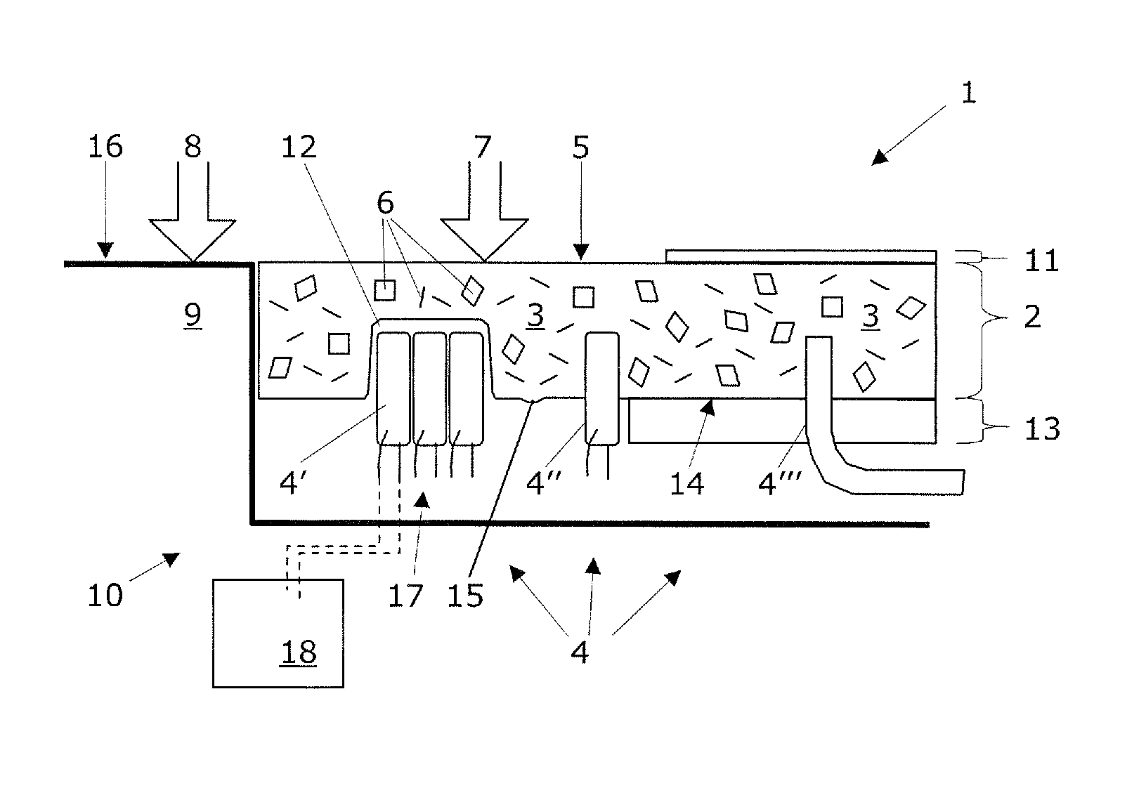
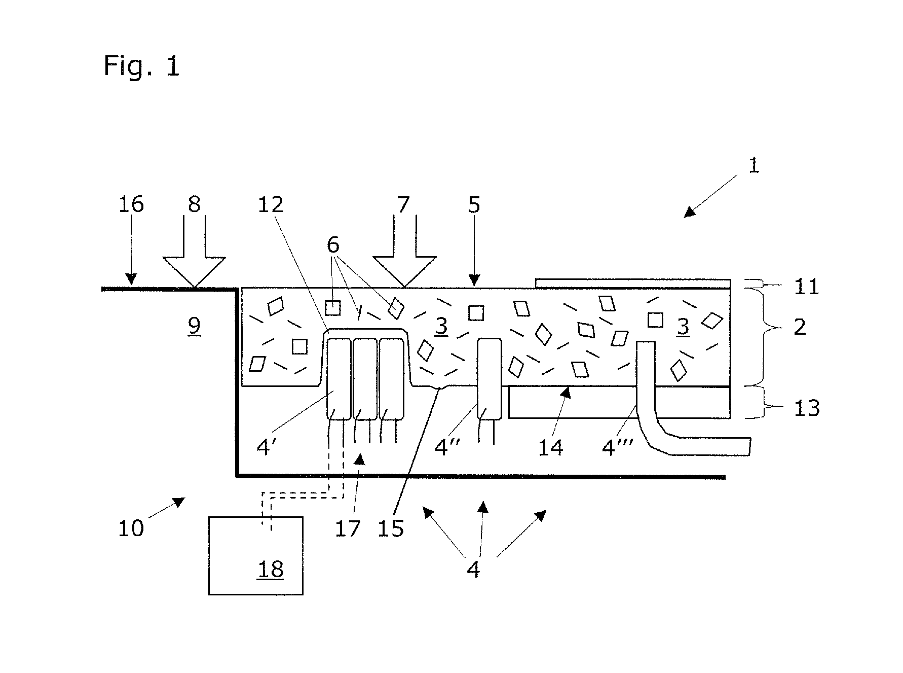
[0013]FIG. 1 shows a plastic component 1 according to the present invention, having a visible part 2 and a light source 4. The visible part 2 is made in one single layer from a plastic molding compound and comprises a transparent or translucent matrix 3. The light source 4 comprises one or more lamp elements 4′,4″,4′″ which are situated under the surface 5 of the visible part 2. The visible part according to the present invention is implemented as essentially opaque in relation to daylight and transparent or translucent in relation to the light emitted by the lamp elements 4′,4″,4′″. For this, the visible part 2 contains admixed effect pigments 6 and thus defines a surface appearance image 7 which, when the light source 4 is inactive, essentially corresponds to the surface appearance image 8 of the remaining wall 9 of an object 10 in which the plastic component 1 is installed. When the light source 4 is active, the surface appearance image 7 of the visible part 2 is essentially dete...


PUM

PropertyMeasurementUnit
transparentaaaaaaaaaa
translucentaaaaaaaaaa
physicalaaaaaaaaaa

Abstract

The present invention relates to a plastic component having a visible part that is made in one single layer from a plastic molding compound and that comprises a transparent or translucent matrix, and having a light source that comprises one or more lamp elements, situated under the surface of the visible part. The visible part is implemented as essentially opaque in relation to daylight and transparent or translucent in relation to the light emitted by the lamp elements. The visible part also contains admixed effect pigments and defines a surface appearance image which, when the light source is inactive, essentially corresponds to the surface appearance image of the remaining wall of an object in which the plastic component is installed and which, when the light source is active, is essentially determined by the light source activity. The plastic component according to the invention is characterized in that the lamp elements are selected from a group which comprises light-emitting diodes, organic light-emitting diodes, and fiber-optic light systems, the lamp elements at least partially being embedded in the plastic molding compound of the visible part. The manifold uses of this plastic component comprise installation in vehicles, paneling elements, and furniture, as well as in housings of greatly varying devices.

Description

RELATED PATENT APPLICATIONS[0001]This patent application claims priority of the German patent application DE 10 2005 047 500.0 that has been filed on Oct. 4, 2005; the entire content of which is enclosed herein by explicit reference.TECHNICAL FIELD OF THE INVENTION[0002]The present invention relates, according to the preamble of independent Claim 1, to a plastic component having a visible part that is made in one layer from a plastic molding compound and that comprises a transparent or translucent matrix, and having a light source, which comprises one or more lamp elements, situated under the surface of the visible part. The visible part is implemented as essentially opaque in relation to daylight and transparent or translucent in relation to the light emitted by the lamp elements and contains admixed effect pigments. Thus, the visible part defines a surface appearance image which, when the light source is inactive, corresponds as much as possible to the surface appearance image of ...

Claims


Application Information

Patent Timeline
Patent Type & Authority Patents(United States)
IPC IPC(8): F21V5/00
CPCB60Q1/26B60Q3/02B60Q3/044B60R13/02B60R13/04B60Q2500/10C08L2205/02C08K3/0041C08L77/00C08L77/02C08L77/06C08L2201/08B60R2013/0287B60Q3/14B60Q3/54C08K3/014
Inventor KAISSER, MICHAELHALA, RALFKAGI, WERNER
Owner EMS CHEM AG
Learn More